Liquid crystal display device

a liquid crystal display and display device technology, applied in the direction of liquid crystal compositions, instruments, chemistry apparatus and processes, etc., can solve the problems of affecting the display effect of the color filter layer on the liquid crystal layer, the effect of increasing the ion density (id) in the liquid crystal layer is considered to be very small, and the display is faulty, so as to reduce the voltage holding ratio (vhr), the effect of increasing the ion density (id) in the liquid crystal

Active Publication Date: 2015-09-01
DAINIPPON INK & CHEM INC
View PDF10 Cites 18 Cited by
  • Summary
  • Abstract
  • Description
  • Claims
  • Application Information

AI Technical Summary

Benefits of technology

[0020]The liquid crystal display device according to the present invention, which includes a specific liquid crystal composition and a color filter including specific pigments, allows a reduction in the voltage holding ratio (VHR) and an increase in the ion density (ID) in a liquid crystal layer to be suppressed, and thereby the occurrence of faulty display such as white missing pixels, alignment inconsistencies, and burn-in is suppressed.

Problems solved by technology

However, the direct effect of a material of the color filter layer on the liquid crystal layer has been considered to be very small compared with the effect of the alignment film material since the alignment film and the transparent electrode are interposed between the color filter layer and the liquid crystal layer.
Therefore, it cannot be said that the color filter layer and the liquid crystal layer are in an environment where they are completely isolated from each other, and the impurities contained in the color filter layer, which migrate via an alignment film and a transparent electrode, may cause a reduction in a voltage holding ratio (VHR) of a liquid crystal layer and an increase in the ion density (ID) in the liquid crystal layer, which results in faulty display such as white missing pixels, alignment inconsistencies, and burn-in.
However, there is not a great difference between these methods and a method of simply reducing the amount of impurities contained in a pigment, and these methods provide unsatisfactory improvements in addressing the faulty display in the present situation in which progress has been made in purification techniques for pigments.
Thus, the issue of faulty display of liquid crystal display devices, which are becoming more advanced, has not yet been addressed.

Method used


Image

  • Liquid crystal display device
  • Liquid crystal display device
  • Liquid crystal display device

Examples


examples

[0173]A part of the preferred embodiment of the present invention is described in detail with reference to Examples below, which do not limit the present invention. In the compositions described in Examples and Comparative Examples below, “%” means “% by mass”.

[0174]The physical properties of a liquid crystal composition are represented as follows.

[0175]TN-I: nematic phase-isotropic liquid phase transition temperature (° C.) as an upper limit temperature of liquid crystal phase

[0176]Δ∈: dielectric constant anisotropy

[0177]Δn: refractive index anisotropy

[0178]η: viscosity (mPa·s) at 20° C.

[0179]dgap: gap (μm) between a first substrate and a second substrate of a cell

[0180]VHR: voltage holding ratio (%) at 70° C.

[0181](the ratio (%) of a voltage measured under the conditions of an applied voltage of 5 V, a frame time of 200 ms, and a pulse width of 64 μs when the liquid crystal composition is injected into a cell having a thickness of 3.5 μm to an initially applied voltage)

[0182]ID: i...

examples 1 to 4

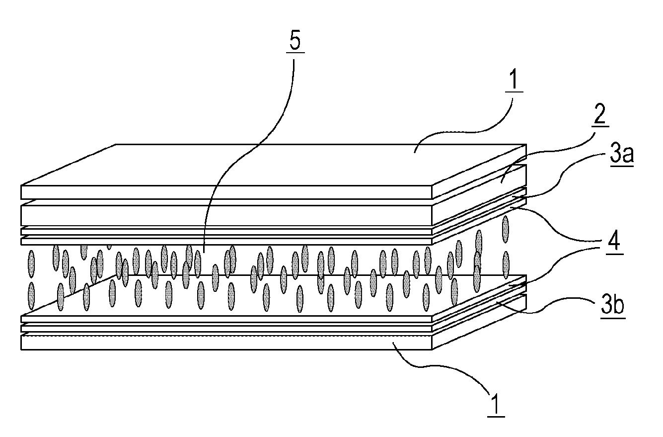
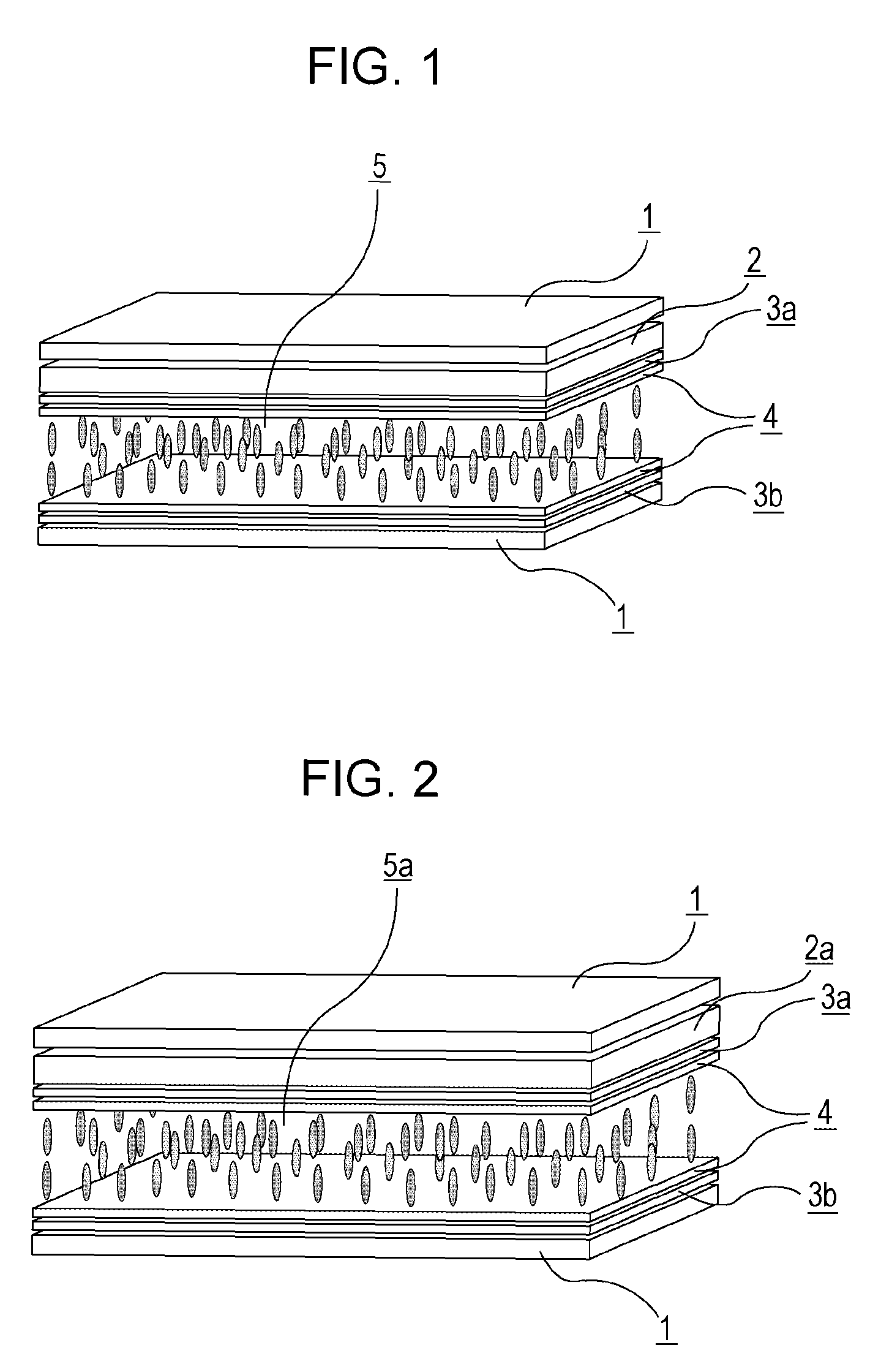
[0223]Electrode structures were formed on the first and second substrates, and alignment films having a vertical alignment were formed on surfaces of the first substrate and the second substrate which face each other. Subsequently, a weak rubbing treatment was performed to form VA cells. A liquid crystal composition 1 shown in Table 9, which had negative dielectric anisotropy, was held between the first substrate and the second substrate. Then, liquid crystal display devices of Examples 1 to 4 (dgap=3.5 μm, alignment film SE-5300) were prepared using the color filters 1 to 4 shown in Table 8. The VHR and ID of each liquid crystal display device were determined. Each liquid crystal display device was evaluated in terms of burn-in. Table 10 shows the results.

[0224]

TABLE 9Liquid crystal composition 10d1-Cy-Cy-3203-Cy-Cy-2153-Cy-Ph—O150d1-Cy-1O—Ph5—O1-Cy-2110d1-Cy-1O—Ph5—O1-Cy-3110d1-Cy-1O—Ph5—O1-Cy-4110d1-Cy-1O—Ph5—O1-Cy-5110d1-Cy-Cy-1O—Ph5—O3d040d1-Cy-Cy-1O—Ph5—O4d040d1-Cy-1O—Ph5—O1-C...

examples 5 to 12

[0239]Liquid crystal display devices of Examples 5 to 12 were prepared by holding any one of the liquid crystals shown in Table 17, which had negative dielectric anisotropy, as in Example 1 and using any one of the color filters shown in Table 8. The VHR and ID of each liquid crystal display device were determined. Each liquid crystal display device was evaluated in terms of burn-in. Tables 18 and 19 show the results.

[0240]

TABLE 17Liquid crystal Liquid crystalcomposition 2composition 33-Cy-1O—Ph5—O211115-Cy-1O—Ph5—O210100d1-Cy-Cy-3200d1-Cy-Cy-5200d3-Cy-Cy-310103-Cy-1═1-Cy-310100d1-Cy-1O—Ph5—O1-Cy-350d1-Cy-Cy-1O—Ph5—O3d050d1-Cy-Cy-1O—Ph5—O4d052-Cy-Cy-1O—Ph5—O2553-Cy-Cy-1O—Ph5—O212124-Cy-Cy-1O—Ph5—O2550d1-Cy-1O—Ph5—O1-Cy-Cy-1d0120d1-Cy-1O—Ph5—O1-Cy-Cy-250d1-Cy-1O—Ph5—O1-Cy-Cy-32Composition ratio total (%)100100Tni / ° C.79.678.9Δn (20° C.)0.0740.075η 20 / mPa · s17.818.2Δε (20° C.)−4.8−4.8

[0241]

TABLE 18Example 5Example 6Example 7Example 8Liquid crystal Liquid crystalLiquid crystal Liquid ...


PUM

PropertyMeasurementUnit
particle sizeaaaaaaaaaa
carbon numberaaaaaaaaaa

Abstract

The present invention provides a liquid crystal display device that allows a reduction in a voltage holding ratio (VHR) of a liquid crystal layer and an increase in an ion density (ID) in the liquid crystal layer to be suppressed and thereby addresses issues of faulty display such as white missing pixels, alignment inconsistencies, and burn-in. The liquid crystal display device according to the present invention, having a feature of suppressing the reduction in a voltage holding ratio (VHR) and the increase in an ion density (ID) in a liquid crystal layer and thereby suppressing occurrence of faulty display such as burn-in, is particularly useful as VA-mode and PSVA-mode liquid crystal display devices for active-matrix driving and may be used for liquid crystal display devices such as a liquid crystal TV, a monitor, a mobile phone, and a smart phone.

Description

TECHNICAL FIELD[0001]The present invention relates to a liquid crystal display device.BACKGROUND ART[0002]Recently, liquid crystal display devices have been widely used in clocks, electronic calculators, various home appliances, measuring equipment, panels for automobiles, word processors, electronic personal organizers, printers, computers, TVs, and the like. Typical examples of the types of liquid crystal display include a TN (twisted nematic)-mode display, a SIN (super-twisted nematic)-mode display, a DS (dynamic light scattering)-mode display, a GH (guest-host)-mode display, an IPS (in-plane switching)-mode display, an OCB (optically compensated birefringence)-mode display, an ECB (electrically controlled birefringence)-mode display, a VA (vertical alignment)-mode display, a CSH (color super-homeotropic)-mode display, and a FLC (ferroelectric liquid crystal) display. There has been a shift in the driving method used from a conventional static driving to a multiplex driving, whic...

Claims


Application Information

Patent Timeline
Patent Type & Authority Patents(United States)
IPC IPC(8): C09K19/30C09K19/42G02B5/20G02F1/1335C09K19/58C09K19/32C09K19/52C09K19/04C09K19/12C09K19/34
CPCC09K19/3066C09K19/3068C09K19/322C09K19/3402C09K19/42C09K19/582G02B5/20G02F1/133512G02F1/133514G02F1/133516C09K2019/0407C09K2019/0448C09K2019/0466C09K2019/122C09K2019/123C09K2019/301C09K2019/3009C09K2019/3016C09K2019/3021C09K2019/3027C09K2019/3036C09K2019/3037C09K2019/3425C09K2019/523G02B5/201
Inventor KANEOYA, MASAKAZUKATEUCHI, KIYOFUMIFUNAKURA, SEIJISHIMADA, KATSUNORI
Owner DAINIPPON INK & CHEM INC
Why Eureka
Try Eureka