
Pretreated cation-exchange resin, treation method of the resin, and mixed bed with cation-exchange resin

a technology cation exchange resin, which is applied in the direction of cation exchanger materials, water/sewage treatment by ion exchange, ion exchangers, etc., can solve the problems of agglomeration, reducing the ion exchange capability of anionic exchange resin, and mutual adhesion of resins

Active Publication Date: 2015-09-08
ROHM & HAAS CO
View PDF13 Cites 0 Cited by
  • Summary
  • Abstract
  • Description
  • Claims
  • Application Information

AI Technical Summary

Benefits of technology

The objective of this patent is to provide a cationic exchange resin that can quickly exchange polyvalent ions (also known as multivalent ions) as well as monovalent ions. This results in a resin that can effectively absorb anionic polymers and prevent channeling, which can occur when there is a buildup of ions and other contaminants on surfaces. The technical effect is a more efficient and effective resin for use in ion-exchange processes.

Problems solved by technology

However, when cationic exchange resin and anionic exchange resin are packed in a given tower, these resins mutually adhere and agglomeration is known to occur.
However, various problems arise such as a decline in the ion-exchange capability of anionic exchange resin when the surface of anionic exchange resin is coated.
For example, the adsorption rate of anionic polymers, which are impurities contained in treated water, as well as the amount of saturation adsorption decline so that adsorption removal of anionic polymers cannot be completed.
Additionally, the reaction rate of anionic exchange resin declines, with the result being that the removal of anionic constituents such as sulfate ions or nitrate ions becomes impossible.

Method used


Image

  • Pretreated cation-exchange resin, treation method of the resin, and mixed bed with cation-exchange resin
  • Pretreated cation-exchange resin, treation method of the resin, and mixed bed with cation-exchange resin

Examples


embodiment 1

[0038 is as follows.

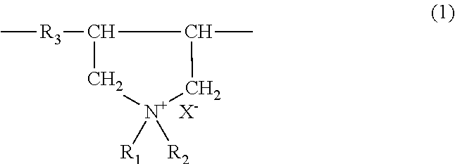
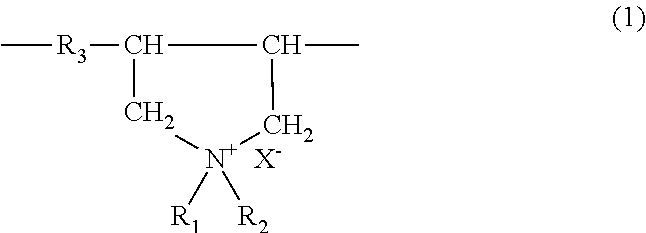
[0039]A column was packed with one liter of strongly acidic cationic exchange resin (proprietary name: Amberjet 1500, hydrogen type) and the column was then filled with deionized water. A total of 60 mg of poly (diallyl dimethylammonium chloride): [PADMAC] (product of Nalco Chemical Co.) having number average molecular weight of 100,000 was dissolved as water-soluble cationic polymer electrolyte in deionized water and then circulated into aforementioned column. This was stirred for one hour at 60° C. under air mixing, followed by adequate washing with deionized water to derive strongly acidic cationic exchange resin treated with water-soluble cationic polymer electrolyte.

[0040]Agglomeration Test: Agglomeration tests pursuant to the method stated in paragraph 0022 of Japanese Kokai Publication Hei-2003-176371 were carried out on the resulting water-soluble cationic polymer electrolyte-treated strongly acidic cationic exchange resin. The results are presented below...

embodiment 2

[0045 is as follows.

[0046]The same operations as in Embodiment 1 were repeated except for the use of 100 mg of poly diallyldimethylammonium chloride instead of the 60 mg of poly diallyl dimethylammonium chloride having number average molecular weight of 100,000 that was used in Embodiment 1. That derived cationic exchange resin whose surface was coated.

[0047]Comparative Examples 1 to 4 are as follows.

[0048]The same operations as in Embodiment 1 were repeated except for the use of compounds presented in Table 1 instead of the 60 mg of poly diallyl dimethylammonium chloride having number average molecular weight of 100,000. That derived cationic exchange resins (the resin of Comparative Example 1 was untreated) whose surfaces were coated.

[0049]

TABLE 1Embodiment or ComparativeType of water-soluble cationic Amount Examplepolymer electrolyte(mg)Embodiment 1PADMAC60Embodiment 2PADMAC100Comparative Example 1(none)—Comparative Example 2poly(vinyl pyridine)ester60Comparative Example 3polyvin...


PUM

PropertyMeasurementUnit
mean volume particle diameteraaaaaaaaaa
temperatureaaaaaaaaaa

Abstract

The present invention provides cationic exchange resin that maintains a high exchange speed of polyvalent ions in addition to monovalent ions without agglomeration occurring in spite of surface coating even when mixed bed ion-exchange resin is used.

Description

[0001]The present invention concerns cationic exchange resin pretreated with specific water-soluble cationic polymer electrolyte as well as mixed bed ion-exchange resin incorporating this.[0002]Mixed bed ion-exchange resin is used in order to remove ionic impurities from liquids in the electronic industry, steam / nuclear power plants and the like. Mixed bed ion-exchange resin has cationic exchange resin and anionic exchange resin packed in the same resin bed. However, when cationic exchange resin and anionic exchange resin are packed in a given tower, these resins mutually adhere and agglomeration is known to occur. When this agglomeration occurs, channeling of the resin (the phenomenon of volumetric expansion without peak density of packed resin due to adhesion of cationic exchange resin and anionic exchange resin) or mutual surface contamination occur.[0003]Various methods have been examined in order to prevent agglomeration. First, a method of coating treatment of the surface of a...

Claims


Application Information

Patent Timeline
Patent Type & Authority Patents(United States)
IPC IPC(8): B01J39/08B01J39/16B01J47/00B01J47/04C02F1/42
CPCB01J39/08B01J39/16B01J47/006B01J47/04C02F1/42C02F2001/427C02F2001/425B01J47/016B01J39/18B01J41/12C08J5/20
Inventor TSUZUKI, SHINTARO
Owner ROHM & HAAS CO
Learn More