
Automotive rearview mirror with capacitive switches

a technology of capacitive switches and rearview mirrors, applied in the field of electrical components, can solve the problem of limited effective field of view of elements

Inactive Publication Date: 2015-09-15
GENTEX CORP
View PDF52 Cites 34 Cited by
  • Summary
  • Abstract
  • Description
  • Claims
  • Application Information

AI Technical Summary

Benefits of technology

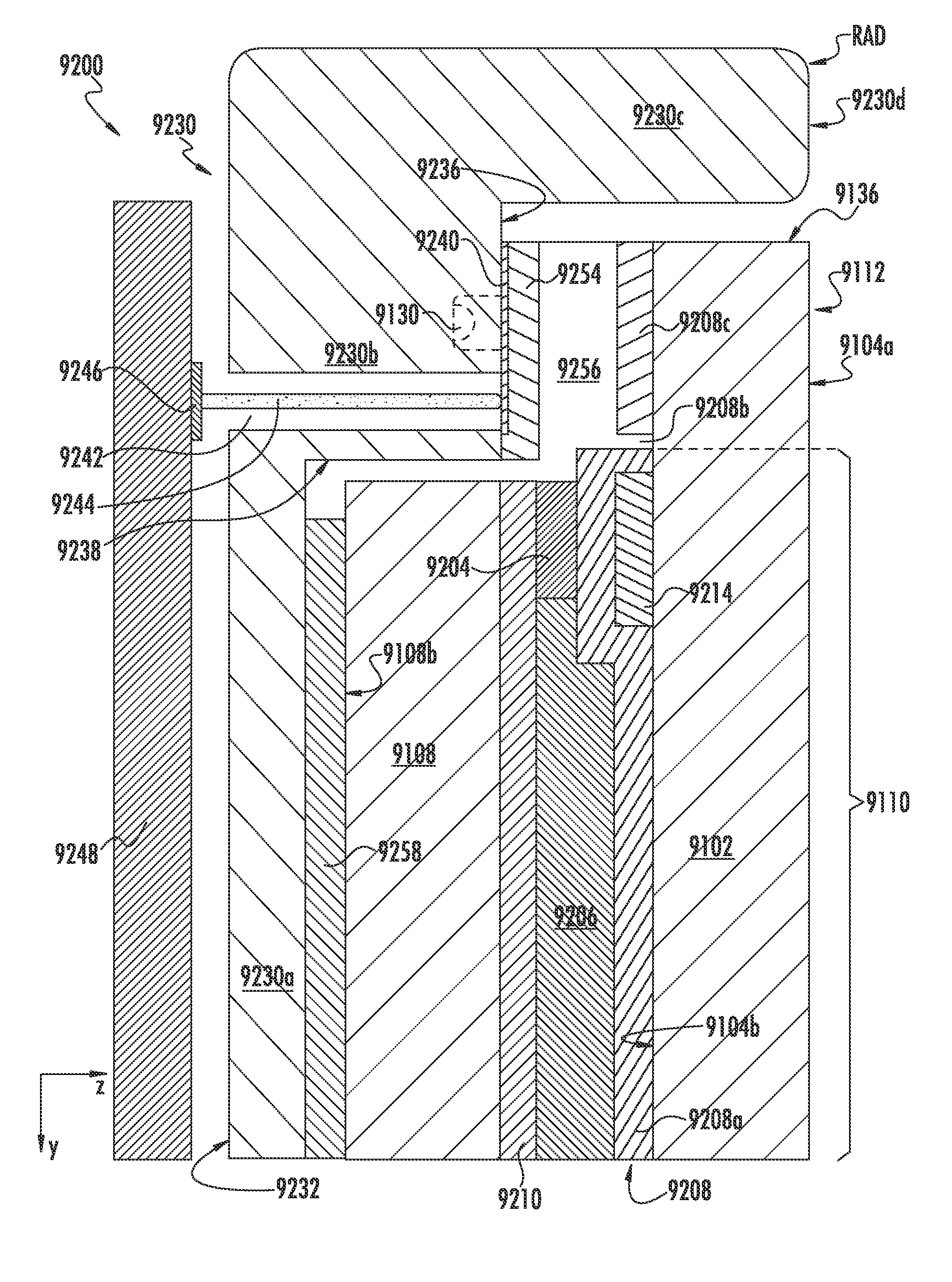
The invention provides a vehicular rearview assembly with an electrochromic element that can be activated to change its optical properties. The assembly includes a first and second optically transparent substrate with a seal that bounds a cavity containing the electrochromic medium. The electrochromic element has a first surface that faces the front of the assembly and a second surface that is smaller than the first surface. The electrochromic element has a curved shape with a radius of at least 2.5 mm. The assembly also includes a conductive pad of a capacitive switch on the second surface of the electrochromic element. The electrochromic element has a first edge surface that is exposed and a non-conductive portion that faces the seal. The assembly may also contain an auxiliary device such as an illumination assembly, display, voice activated system, compass system, telephone system, highway toll booth interface, telemetry system, headlight controller, rain sensor, tire pressure monitoring system, navigation system, lane departure warning system, or adaptive cruise control system. The electrochromic element can be activated to change its optical properties, such as its light transmission or reflectance, by applying a voltage to the sealed cavity.

Problems solved by technology

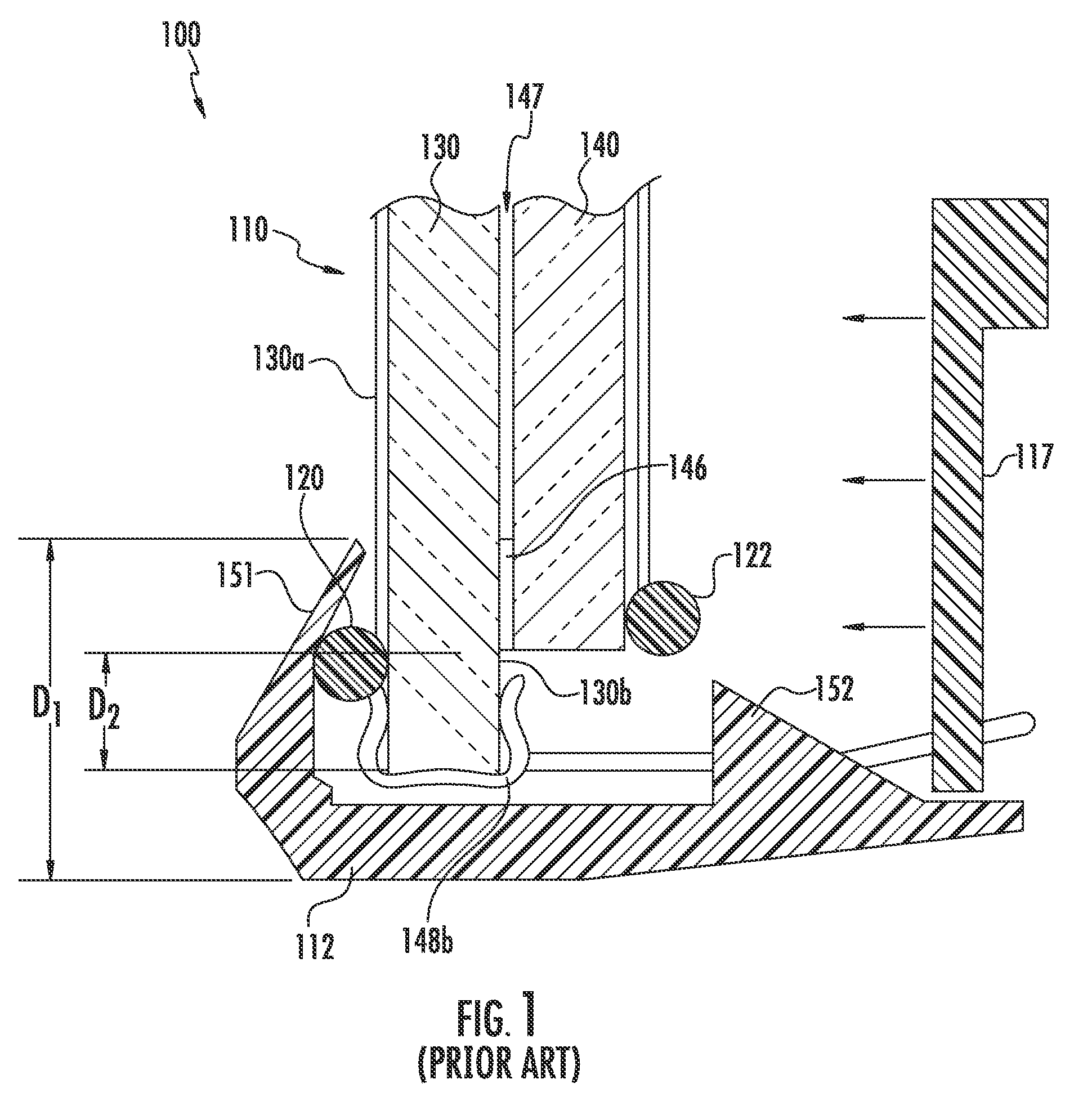
Often, the effective field of view of the element is limited, at least in part, by the construction of the element itself and / or an associated bezel.

Method used


Image

  • Automotive rearview mirror with capacitive switches
  • Automotive rearview mirror with capacitive switches
  • Automotive rearview mirror with capacitive switches

Examples


example 1

[0385]Environmentally stable and low-cost Chromium is used as the base metal. A thin film program was used to calculate the resultant color and reflectance of light for the different 3 nm-thick RE-metallic layers. The results are summarized in Table 16.

[0386]

TABLE 16StructureReflectancea*b*Reference (Glass +52.3−1.9−0.7chrome base layer)Reference +RE-layer made of . . .cobalt54.3−1.60.5chrome52.3−1.9−0.7iridium54.8−1.80.6Mo50.1−1.41.5Ag with 7% Au57.4−1.7−0.3Au54.7−2.12.1Cd56.7−1.7−0.6Cu54.4−1.30.3SnCu 505055.2−1.70.2CuZn 505055.0−1.70.9Nb50.9−1.41.4Pd55.2−1.60.3Ru54.9−1.60.2Pt53.9−1.60.8Rhenium47.6−1.24.3Rh55.7−1.40.4Ta50.2−1.62.1Ag56.9−1.7−0.2Al62.2−1.5−0.9Al:Si 60:4053.2−1.60.3Al:Si 90:1058.3−1.7−0.3Al:Ti 50:5051.8−1.70.9Al:Ti 70:3051.7−1.61.3Ge47.4−1.9−1.1Ni53.8−1.70.8Ti52.7−1.80.4W49.2−1.73.1V49.4−0.70.8Zn56.7−3.1−1.1Zr51.7−1.9−0.7

[0387]FIG. 30A graphically shows a corresponding change in reflectance of the considered structures of Table 16 with n (real part of the index of the...


PUM

PropertyMeasurementUnit
radiusaaaaaaaaaa
forceaaaaaaaaaa
forceaaaaaaaaaa

Abstract

A vehicular rearview assembly that has a rounded outer perimeter edge to satisfy safety standards and contains an EC element having a complex peripheral ring, a front surface that is fully observable from the front of the assembly, and a user interface with switches and sensors that activate and configure, in cooperation with electronic circuitry of the assembly, pre-defined function(s) or device(s) of the assembly in response to the user input applied to the user interface. A complex peripheral ring may include multiple bands the structures of which is adapted to provide for specified optical characteristics of light, reflected off of the ring. Electrical communications between the electronic circuitry, the mirror element, and the user interface utilize connectors configured to exert a low contact force, onto the mirror element, limited in part by the strength of adhesive affixing the EC element to an element of the housing of the assembly.

Description

[0001]This application claims the benefit of U.S. patent application Ser. No. 12 / 832,838 filed on Jul. 8, 2010 and titled “Vehicular Rearview Mirror Elements and Assemblies Incorporating These Elements”, U.S. Provisional Patent Applications No. 61 / 450,888 filed on Mar. 9, 2011 and titled “Automotive Rearview Mirror With Capacitive Switches”, and U.S. Provisional Patent Application No. 61 / 467,832 filed on Mar. 25, 2011 and titled “Automotive Rearview Mirror with Capacitive Switches”.[0002]This application is also a continuation-in-part of U.S. patent application Ser. No. 12 / 832,838 filed on Jul. 8, 2010, which is a continuation-in-part of U.S. patent application Ser. No. 12 / 750,357 filed on Mar. 30, 2010, which is a continuation of U.S. patent application Ser. No. 12 / 154,736 filed on May 27, 2008 and now issued as U.S. Pat. No. 7,719,750, which is a continuation of U.S. patent application Ser. No. 11 / 477,312 filed on Jun. 29, 2006 and now issued as U.S. Pat. No. 7,379,225, which is a...

Claims


Application Information

Patent Timeline
Patent Type & Authority Patents(United States)
IPC IPC(8): G02F1/15B60R1/08G02F1/153G02F1/161G02F1/157
CPCG02F1/157B60R1/088G02F1/1533G02F1/161B23K26/362B23K26/402B23K2103/00B23K2103/50
Inventor TONAR, WILLIAM L.BUGNO, MARK D.ROTH, MARK R.CAMMENGA, DAVID J.MINIKEY, JR., DANNY L.STRAY, JOEL A.NEUMAN, GEORGE A.
Owner GENTEX CORP
Learn More