Flexible spine components

a technology of spine components and flexible rods, applied in the field of flexible rod connectors, can solve the problems of limited flexibility in all directions, and achieve the effects of increasing the flexibility of the component, increasing the width, and reducing the risk of injury

Inactive Publication Date: 2015-09-22
FLEX TECH
View PDF18 Cites 4 Cited by
  • Summary
  • Abstract
  • Description
  • Claims
  • Application Information

AI Technical Summary

Benefits of technology

[0016]A plurality of slots can be employed thereby increasing the flexibility of the component, relative to a shaft having a single slot of identical pattern. The serpentine path forms a plurality of teeth and complimentary recesses on opposite sides of the slot. The slot has sufficient width to form an unbound joint permitting limited movement in any direction between the teeth and the recesses, thereby providing limited flexibility in all directions upon application of tensile, compressive, and / or torsion forces to said component. In a similar manner the slot can have increased width in one direction compared to another direction thus providing increased flexibility in one direction.
[0017]The flexible component can have different degrees of flexibility along the length of said shaft. The varied flexibility can be achieved by having the pitch of the helical slot vary along the length of the shaft. The varied flexibility corresponds to the variation in the pitch of the helical slot. The helical path can have a helix angle in the range of about 10 degrees to about 45 degrees, and the helix angle can be varied along the length of the shaft to produce correspondingly varied flexibility. Alternatively, the width of the helical slot can vary along the length of the shaft to provide the varied flexibility. The rigidity of the flexible shaft can be achieved through the design of the slot pattern, thereby enabling the use of thinner walls than would otherwise be require to produce equivalent rigidity. In a preferred embodiment, the ratio of the amplitude of the serpentine path to the pitch of the slot is in the range from greater than 0.1 to about 0.8.
[0018]The slot can be filled with a resilient material, partially or entirely along the path of the slot. The resilient material can be an elastomer compound which can be of sufficient thickness to fill the slot and to encapsulate the entire shaft thus forming an elastomer enclosed member. The elastomer can be a resilient material such as a urethane or a silicone compound. The rigidity of the flexible shaft can be further achieved or varied through the use of filler material having different stiffness properties, thereby enabling the use of thinner walls than would otherwise be require to produce equivalent rigidity.
[0021]An important aspect of this invention therefore lies in providing a prosthesis for total replacement of a vertebral body and adjacent discs that will provide the flexibility and stiffness of the resected vertebra and, when properly in place, provides a stress environment at the prosthesis / bone interface similar to normal in vivo conditions. Specifically, the invention can be utilized to produce an implant in which the normal ranges of movement are preserved, the prosthesis permitting limited longitudinal flexure, slight compression and expansion, and even a limited degree of torsional movement that at least approximates a normal vertebral response.

Problems solved by technology

The slot has sufficient width to form an unbound joint permitting limited movement in any direction between the teeth and the recesses, thereby providing limited flexibility in all directions upon application of tensile, compressive, and / or torsion forces to said component.

Method used


Image

  • Flexible spine components
  • Flexible spine components
  • Flexible spine components

Examples


Embodiment Construction

[0078]While the present invention will be described more fully hereinafter with reference to the accompanying drawings, in which particular embodiments and methods of implantation are shown, it is to be understood at the outset that persons skilled in the art can modify the invention herein described while achieving the functions and results of this invention. Accordingly, the descriptions that follow are to be understood as illustrative and exemplary of specific structures, aspects and features within the broad scope of the present invention and not as limiting of such broad scope.

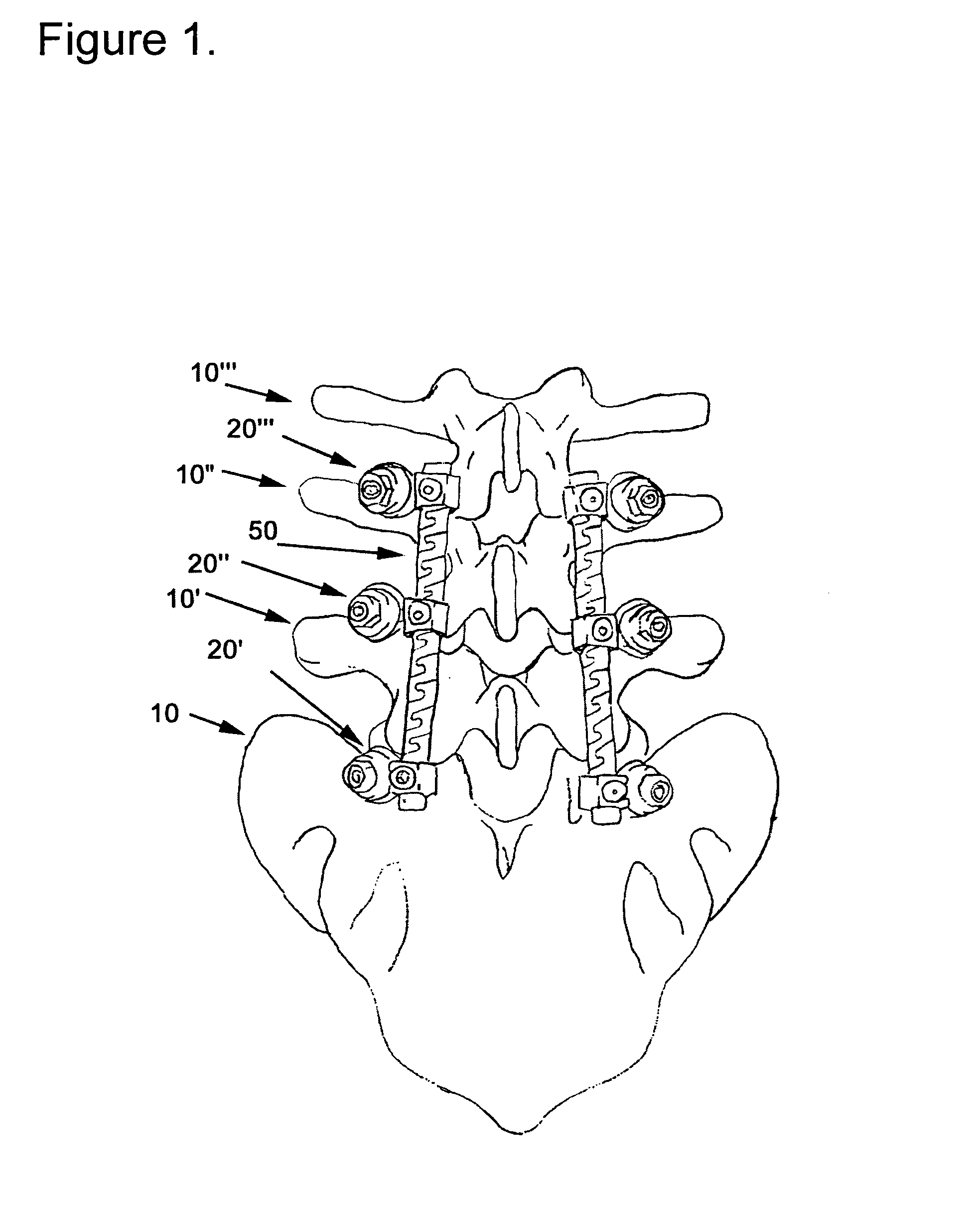
[0079]The present invention is directed to dynamic stabilization systems for use with the anterior, antero-lateral, lateral, and / or posterior portions of at least one motion segment unit of the spine. The systems of the invention are designed to be conformable to the spinal anatomy and provide controlled, dynamic stabilization.

[0080]The system of the invention can be used on the cervical, thoracic, lumbar...


PUM


Abstract

An improved flexible component used for dynamic stabilization of spinal segments for the treatment of vertebrae deformities and injuries and for the replacement of a complete or segment of the body of a vertebra in the spine is described. The flexible component is comprised of a solid, suitable implant material with a longitudinal bore the entire length and an appropriately formed slot which extends spirally around the shaft either continuously or segmentally. The flexible component may be encapsulated, fully or partially, in a suitable implant grade elastomeric resilient material. When used for a dynamic stabilization device, the component is attached to the vertebral bodies by pedicle screws know to those in the art. When used as a vertebral replacement device, attached to the component's opposite ends are members for attachment to the adjacent vertebra that allow for height and angular adjustment.

Description

FIELD OF THE INVENTION[0001]This invention relates to spinal implants to improved flexible elements for the incorporation in spinal implants. Specifically the invention relates generally to flexible rod connectors for dynamically stabilizing a portion of the spine stabilizing two or more bone segments, or use as a vertebral body replacement implant for the replacement of one or multiple spinal vertebra which can possess, at least in one direction, the stiffness properties of the vertebra / disc combination.BACKGROUND OF THE INVENTIONBrief Description of the Prior ArtFlexible Fixation Device[0002]The use of fixation devices for the treatment of vertebrae deformities and injuries is well known in the art. Various fixation devices are used in medical treatment to correct curvatures and deformities, treat trauma and remedy various abnormal spinal conditions. Spinal fusion is the standard method of treatment for conditions including spondylolysis, spinal stenosis and other disc disorders. ...

Claims


Application Information

Patent Timeline
Patent Type & Authority Patents(United States)
IPC IPC(8): A61B17/70A61F2/44A61F2/30
CPCA61B17/7028A61B17/7029A61F2/44A61B17/7031A61B17/7041A61F2/4425A61F2002/3055A61F2002/30405A61F2002/30563A61F2002/30566A61F2002/30649A61F2002/30841A61F2220/0025A61F2310/00011A61B2017/564
Inventor KRAUSE, WILLIAM R.
Owner FLEX TECH
Why Eureka
Try Eureka