Scribing method using blasting machine

a laser scribing and blasting machine technology, applied in the field of scribing methods, can solve the problems of limiting the application of materials, requiring a considerable initial investment, and complicated processing apparatus used for laser scribing

Active Publication Date: 2015-09-29
FUJI MFG CO LTD
View PDF10 Cites 2 Cited by
  • Summary
  • Abstract
  • Description
  • Claims
  • Application Information

AI Technical Summary

Benefits of technology

[0035]Consequently, this eliminates the need for masking, which is required in the scribing by the conventional blasting, and removal of a mask material. In accordance with the reduction in the number of processes, drastic reduction in process cost and working hours are achieved.
[0036]In scribing according to the method of the present invention, since a consumable part is an abrasive only, a stable process with maintaining the process accuracy can be continuously performed by exchanging or replenishing consumed abrasives. Different from the mechanical scribing described as the related art, the scribing according the present invention did not frequently suspend work due to exchange of the consumable part, thus improving productivity.
[0037]In the configuration that sucks and recovers the abrasive and cutting chip powder on the workpiece W in the ejection position of the abrasive by the ejection nozzle 20 in a vicinity of the surface of the workpiece W, a change in process accuracy due to presence of the remaining abrasive and dust can be prevented and scribing without leaving an adhering material on the surface of the workpiece W is achieved. This allows reduction in a failure due to the remaining adhering material.
[0038]Use of an abrasive with a high-specific gravity improves straightness of the abrasive after ejection from the ejection nozzle and allows highly accurate scribing. Especially, use of an abrasive with a specific gravity equal to or more than 5 allowed forming a groove with a width approximately equal to or less than 2.5 times the width of the ejection opening of the ejection nozzle.
[0040]In the case where the workpiece W is a photoelectric conversion layer (for example, a compound photoelectric, conversion layer such as CIGS) formed on a conducting layer (for example, an Mo layer) of the solar cell and has lower hardness than the conducting layer, use of an abrasive with a higher hardness than the photoelectric conversion layer and with a lower hardness than the conducting layer (for example, an abrasive made of stainless steel) allowed selectively removing the photoelectric conversion layer only, without damaging the conducting layer (an under layer) formed under the photoelectric conversion layer.
[0041]A blasting machine 1 according to the present invention includes the ejection nozzle 20. The ejection nozzle 20 includes a first flat surface 24, an inclined surface 25, and a second flat surface 26 that define a rectifying portion 23. Although this configuration includes a narrow ejection opening 21 with a slit width of 10 μm to 500 μm, this preferably allowed preventing the clogging of the abrasive in the ejection nozzle 20.

Problems solved by technology

A processing apparatus used for the laser scribing is complicated and expensive apparatus, thus requiring a considerable initial investment.
Moreover, since the laser scribing is a process using heat, the laser scribing may deform the workpiece or change the workpiece in quality, therefore, there is a restriction to applicable material or the like.
There is a difficulty in a process of a transparent material where adjustment of the focal point of the laser is difficult.
Also, this may cause a dross (a weld deposit of a melted material) to malfunction of the product or similar failure.
As the work proceeds, a tool such as expensive grinding wheel wears out, and process accuracy changes even the wear of the tool is slight, therefore, the tools are required to be exchanged frequently.
This requires a considerable running cost and stop of work during exchanging the tool, reducing productivity.
On the other hand, in the case where a groove is formed by blasting in the known method without performing the above-described masking and using the known blasting machine, a groove with a width equal to or less than 1 mm cannot be formed.
There is no existing blasting method that allows forming a fine groove, which is required in the above-described manufacture of solar cell or the like, without masking.

Method used


Image

  • Scribing method using blasting machine
  • Scribing method using blasting machine
  • Scribing method using blasting machine

Examples


example 1

Scribing Glass Substrate

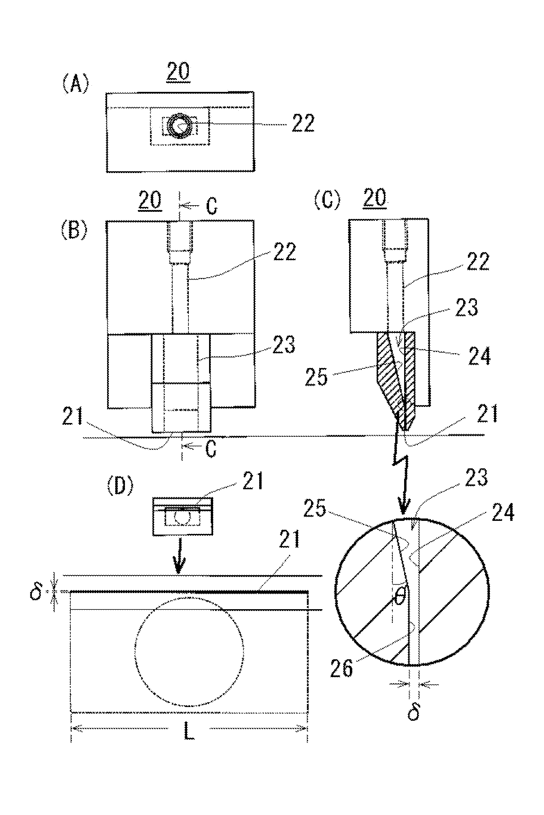
[0086]An ejection nozzle with a slit-shaped ejection opening with a width 40 μm and a length 7 mm was disposed at an ejection distance of 0.3 mm to the surface of a glass substrate (6.5 by new Mohs hardness (hereinafter, all hardness will be indicated by “new Mohs hardness”)) where masking was not performed. The process was performed while the abrasive (WA#3000: hardness of 12 and median diameter of 4 μm) was ejected at an ejection quantity of 0.6 g / min and an ejection pressure of 0.5 MPa while moving the ejection nozzle at the moving speed of 3 m / min in the longitudinal direction of the ejection opening. The volume of the abrasive relative to the discharge gas amount was as described above.

[0087]As a result of scribing by the above-described method, a groove with a width 80 μm and a depth 10 μm was precisely formed by directly ejecting the abrasive on the glass substrate without the masking.

Example 2

Scribing Photoelectric Conversion Film of Solar Cell

[0088]I...

example 2

Test

[0091]

TABLE 1Scribing test on the photoelectric conversion film of a solar cellProcessing stateAbrasiveWidth of SpecificEjectioncut-offMate-gravityquantitylineGeneralProcessing rial Hardness(g / cm3)(g / min)(μm)commentstateStain-4.5 to 57.61.580ExcellentOnly CIGS lessfilm steelremovedGlass6.52.50.5250GoodOnly CIGS film removedZircon93.540.6140SlightlyMo film BadpartiallypeeledWA123.850.6160BadMo film alsoremovedNotice: The particle shape of WA is polygonal while the particle shapes of the others are spherical. As described above, the Mo film was removed by cutting with the WA, however, cut-off lines with a constant width and depth were able to be formed.

[0092]As results described above, even in the case where the abrasives were directly ejected without masking, scribing a groove with a width equal to or less than 1 mm, which had been conventionally impossible, was succeeded in examples using any abrasive.

[0093]However, a conducting layer with a high hardness (an Mo layer) was forme...


PUM

PropertyMeasurementUnit
lengthaaaaaaaaaa
pressureaaaaaaaaaa
specific gravityaaaaaaaaaa

Abstract

To provide a scribing method by blasting that allows forming a groove at high accuracy without masking, a blasting machine that includes an ejection nozzle having a slit-shaped ejection opening with a width of 10 to 500 μm and a length of 5 to 5000 times the width, and an abrasive with a median diameter equal to or less than one-half of a width of the ejection opening of the ejection nozzle and with a maximum particle diameter smaller than a width of the ejection opening are used; and the abrasive is ejected together with compressed gas on a surface of a workpiece at an ejection distance of 0.1 to 3.0 mm and an ejection pressure of 0.2 MPa to 0.6 MPa without masking so that 0.25 cm3 or less of the abrasive is included per 1000 cm3 of the compressed gas discharged from the ejection nozzle.

Description

BACKGROUND OF THE INVENTION[0001]1. Field of the Invention[0002]The present invention relates to a scribing method for forming a groove and a cut-off line on a workpiece and a blasting machine used for the scribing. More specifically, the present invention relates to a scribing method by blasting that ejects an abrasive together with compressed gas and a blasting machine used for the method.[0003]2. Description of the Related Art[0004]A scribing, which forms a groove and a cut-off line on a workpiece, is used to form a groove serving as a break starting point when a hard brittle material such as a glass is cut. The scribing is also used to cut and divide a conductive film and a semiconductor film formed on a substrate into a predetermined pattern during fabrication of a semiconductor device or similar case.[0005]The following describes an exemplary solar cell as one example of the semiconductor device. A solar cell panel includes a conducting layer, a photoelectric conversion layer,...

Claims


Application Information

Patent Timeline
Patent Type & Authority Patents(United States)
IPC IPC(8): B24C1/04B24C5/04
CPCB24C1/045B24C5/04Y02E10/541B24C7/0038B24C1/04B24C7/00
Inventor MASE, KEIJIHINATA, MASATO
Owner FUJI MFG CO LTD
Why Eureka
Try Eureka