Compact OMT device

a technology of electromagnetic signal processing and compact structure, which is applied in the direction of coupling devices, electrical equipment, and antennas, can solve the problems of reducing the power handling of the device, assembling problems of the feed system using the above-mentioned types of omt devices, and reducing the power handling drastically. , to achieve the effect of high power handling solution, increased multipaction risk, and cost-effective manufacturing

Active Publication Date: 2015-09-29
EUROPEAN SPACE AGENCY
View PDF8 Cites 11 Cited by
  • Summary
  • Abstract
  • Description
  • Claims
  • Application Information

AI Technical Summary

Benefits of technology

[0011]The OMT device further comprises a first waveguide portion having the same cross-section as said guide section, said first waveguide section being capable of supporting two orthogonal linear polarization modes of signal propagation, and said first waveguide section extending between said first lengthwise open end of the guide section and a septum. The septum of the OMT extends from an end of the first wave guide portion towards the second lengthwise open end of said guide section and divides said guide section into a second waveguide portion and a third waveguide portion having cross-sections smaller than the cross-section of said first wave-guide portion. For minimal power losses, the septum may be a metallic sheet or thin plate. By way of example, the septum may also be a dielectric sheet.
[0018]The OMT device of the present invention has a compact configuration which embodies a waveguide able to extract or combine two orthogonal linear polarizations with a single integrated septum. Thus, no resonant structures such as irises or metallic slots are required to split orthogonal polarizations. It is also an advantage that the entire phase shift effect is caused by a single component with increasing height that causes at the same time the phase shifting effect and separates the waveguide section into the second and third waveguide section for the propagation of the splitted signals. As a consequence, the compact OMT device has a high power handling and is cost-efficient to manufacture. Furthermore, the waveguide access of the compact OMT is perfectly parallel enabling an easy and very compact assembly of multi-feed arrays in contrast to conventional OMT devices with perpendicular waveguide access.
[0024]The compact OMT offers a compact size in the X and Y axis (with Z being the propagation axis). The compact OMT is cost-efficient to manufacture, as standard milling or spark erosion in aluminum could be used. The compact OMT is a high power handling solution, because it requires no coupling slots or metallic poles which would drastically increase the multipaction risk in the areas where they are located. Furthermore, the electric field inside a component rotates making a multipactor breakdown very difficult to take place. The compact OMT is a low-loss waveguide component, as the waveguide paths are minimal and there are no lossy waveguide recombination networks with magic-tees, bends. The two waveguide port access of the compact OMT are completely parallel, no waveguide twists and bends were necessary, which not only would increase the mass, but in addition would additionally degrade the insertion and return loss. The feeder waveguides that link the antenna to the repeater are easy to accommodate. Finally, the compact OMT is a low-mass solution. A component is made by a square waveguide with a stepped metallic septum in the middle which advantageously results in a very low-mass device.

Problems solved by technology

The cluster of feeds is arranged closely side by side causing implementation problems due to their often complex shape, especially when a great number of feeds are used in a compact configuration.
However, feed systems using the above types of OMT devices face assembling problems, e.g., due to the need for complicated waveguide networks to recombine all the ports, especially when a great number of signal sources have to be fed and when the sources are close to each other.
This type of OMT apparatus is more compact than the complex OMTs but requires a coupling area with a slot iris of small dimensions that reduces drastically the power handling of the device.

Method used


Image

  • Compact OMT device
  • Compact OMT device
  • Compact OMT device

Examples


Embodiment Construction

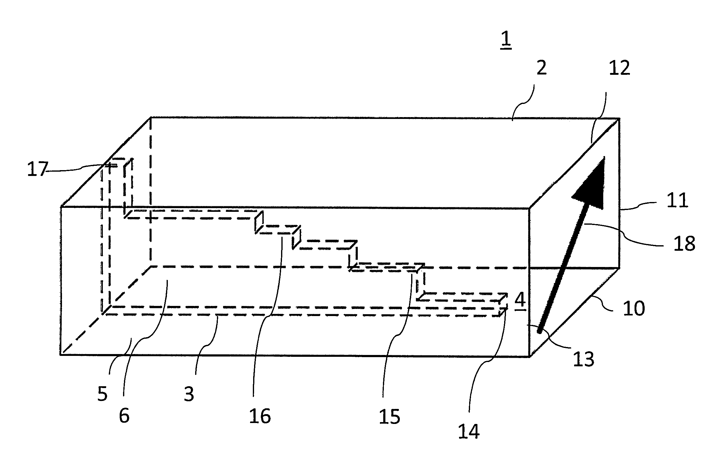
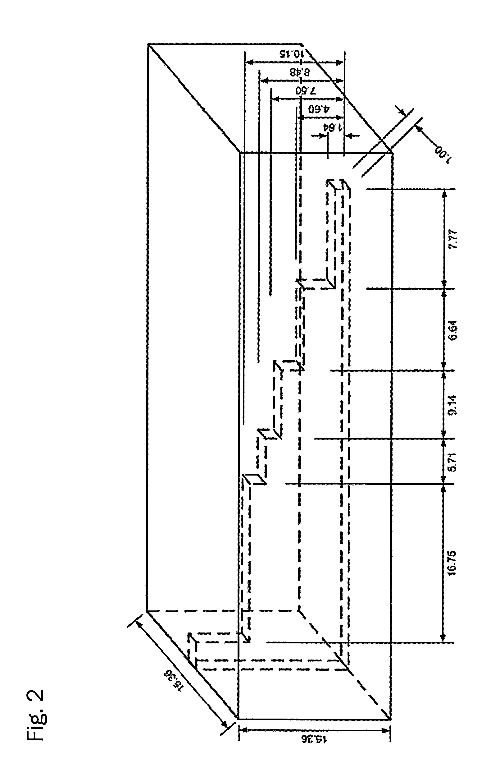
[0034]FIG. 1 illustrates a perspective side view of a compact OMT according to an embodiment of the invention. In the exemplary embodiment depicted in FIG. 1, the orthomode transducer 1 comprises an elongate piece of a hollow electrically conductive waveguide 2 having a square cross-section. The four walls of the waveguide are designated 10, 11, 12, and 13, as shown. A thin elongated electrically conductive septum 3 extends along the longitudinal axis of the compact OMT and forms a plane that is situated halfway between walls 11 and 13. This particular septum 3 has a step-shaped portion causing the septum 3 to be successively increasing in height between the walls 10 and 12.

[0035]The waveguide portion between a first open end of the waveguide (indicated by the black arrow in FIG. 1) and the starting point 14 of the septum form the first waveguide portion 4 that has the same cross-section as the guide section 2. The cross-section of the first waveguide portion 4 (which is the corresp...


PUM


Abstract

Embodiments are disclosed of an orthomode transducer (OMT) device for splitting a linear orthogonally polarized electromagnetic signal into a plurality of linearly polarized frequency components and vice versa. The device comprises a rectangular or circular guide section having a constant cross-section perpendicular to a lengthwise direction of said guide section and first and second lengthwise opposed open ends, a septum that is successively increased in height; extending from an end of the a waveguide portion towards a second lengthwise open end of the guide section, wherein that the plane of said septum is provided at an angle of 45 degrees relative to the polarization axes of the orthogonal linear polarization modes and said septum induces a differential phase shift of substantially 180 degrees or a multiple thereof between components of the linear polarization modes that are perpendicular to said septum and components that are parallel to said septum.

Description

CROSS-REFERENCE TO RELATED APPLICATIONS[0001]This application is the U.S. National Stage entry under 35 U.S.C. §371 of international application PCT / EP2010 / 007045, filed 19 Nov. 2010, which in turn claims priority to European patent application EP 09178229.2, filed 7 Dec. 2009.FIELD OF THE INVENTION[0002]The present invention relates to a waveguide apparatus for electro-magnetic signal processing and more especially to an apparatus capable of dividing an orthogonally polarized electro-magnetic signal into two linearly polarized signals and, in reverse direction, capable of combining two linearly polarized signals into an orthogonally polarized electro-magnetic signal.BACKGROUND OF THE INVENTION[0003]In the art of satellite communications, the modern antennas on board of satellites are frequently implemented by an active / passive array of feeds in the focal plane of a reflector system when using orthogonally polarized signals in the feed systems. The cluster of feeds is arranged close...

Claims


Application Information

Patent Timeline
Patent Type & Authority Patents(United States)
IPC IPC(8): H01P1/161H01P1/165H01Q15/24H01P1/213
CPCH01P1/161H01P1/165H01P1/2131H01Q15/246
Inventor DELGADO, PABLO SARASA
Owner EUROPEAN SPACE AGENCY
Why Eureka
Try Eureka