Extreme ultraviolet source with magnetic cusp plasma control

a plasma control and ultraviolet light technology, applied in the direction of x-ray tubes, electrical equipment, electric discharge tubes, etc., can solve the problems of inability to extend the heat pipe containment technology to tin sources, inability to work effectively with heat pipes, and inability to handle heat pipes. to achieve the effect of maximizing the power that can be handled and large area

Active Publication Date: 2015-10-06
PUREX
View PDF22 Cites 2 Cited by
  • Summary
  • Abstract
  • Description
  • Claims
  • Application Information

AI Technical Summary

Benefits of technology

[0009]3) The plasma outflow is guided by the radial magnetic field onto an annular plasma beam dump that can have a large area, maximizing the power that can be handled.

Problems solved by technology

However, the heat pipe containment technology cannot be extended to tin sources because the heat pipe temperature would have to be 1300 C to provide the equivalent tin vapor pressure versus 750 C for lithium.
This vastly higher working temperature renders the heat pipe approach essentially unworkable for tin whereas it is very practicable for lithium.
Two things begin to go wrong: 1) there is an EUV absorption cross section of 2×10⁻¹⁷ cm2 for tin atoms that causes increasing EUV absorption loss as the plasma density builds, and 2) the mirror magnetic trap is unstable [14] to lateral plasma loss, which can expose the collection optic to tin atoms.
However, only a relatively constricted path is available for plasma exhaust toward one end of such a trap configuration, implying a limited heat removal capacity.
Other magnetic configurations [27,29] have been designed to protect the collection optic, but these rely on gas cooling, and do not provide a specific path for plasma flow toward a large area plasma beam dump.
Accordingly, the power scaling of such configurations is limited due to lack of heat removal.
One of the main buffer gases used has been hydrogen [13,33] but as plasma power increases there is an increasing fraction of molecular hydrogen dissociation that can lead to vacuum pumping and handling problems of reactive hydrogen radicals.

Method used


Image

  • Extreme ultraviolet source with magnetic cusp plasma control
  • Extreme ultraviolet source with magnetic cusp plasma control
  • Extreme ultraviolet source with magnetic cusp plasma control

Examples


Embodiment Construction

[0035]Herein the corresponding like elements of different realizations of the invention are labeled similarly across the drawing set, and will not always be listed in their entirety.

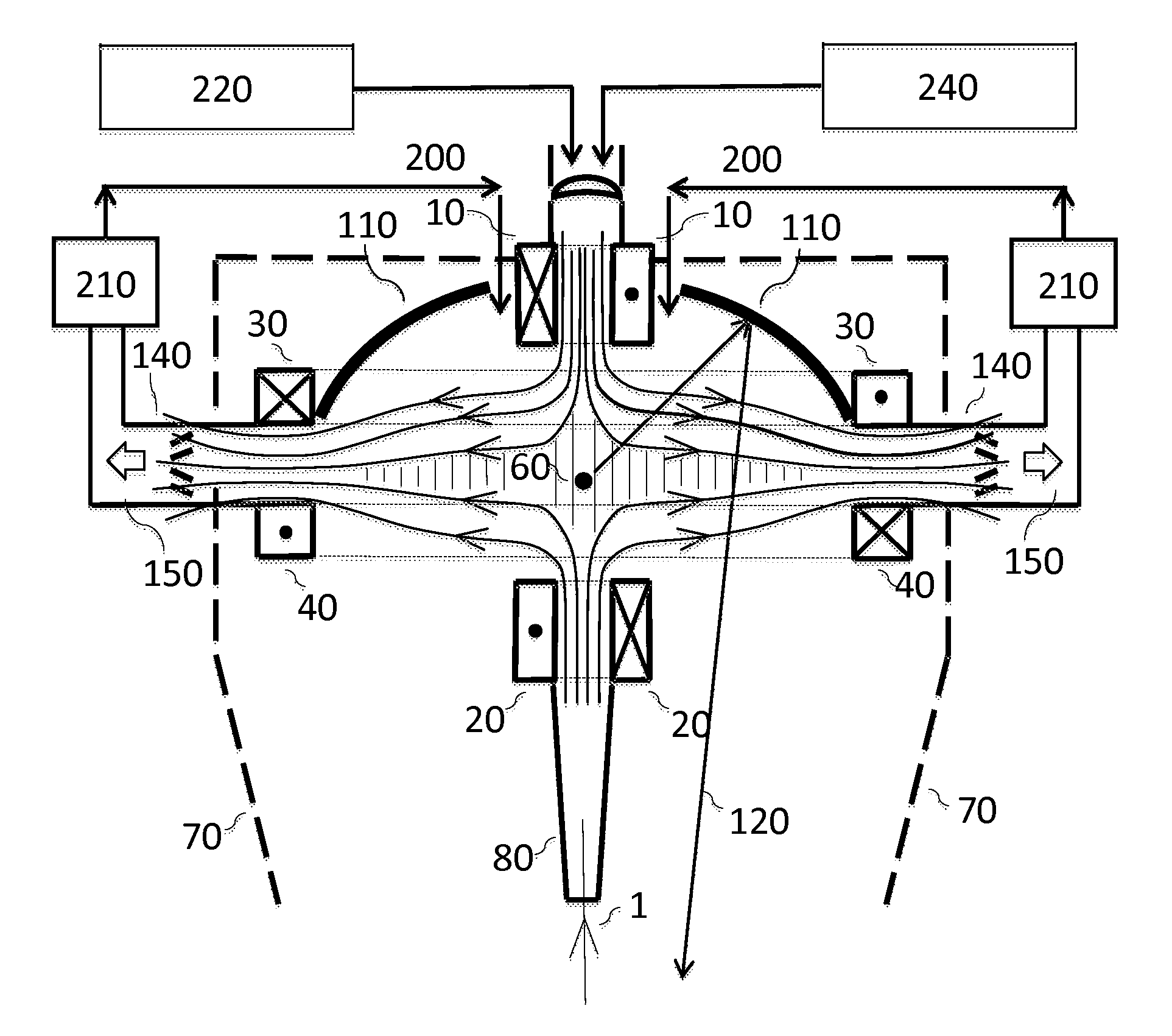
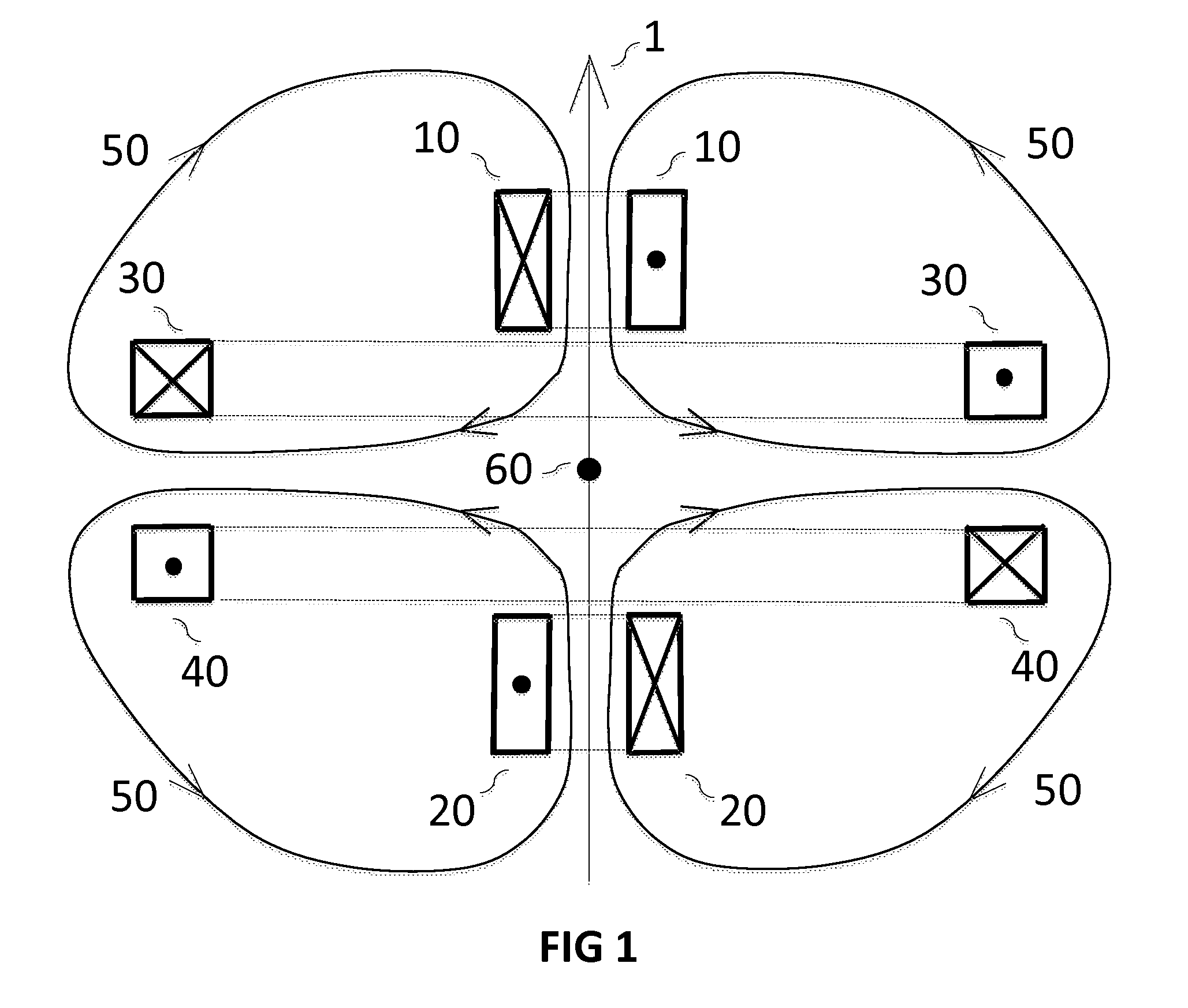
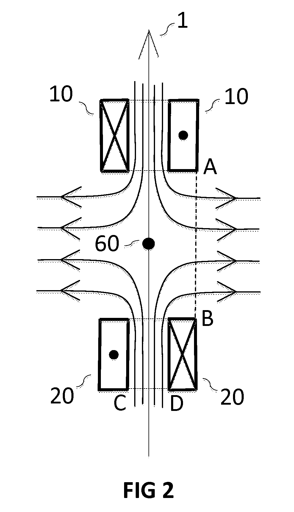
[0036]We describe the underlying magnetic field configuration in its first, symmetric, embodiment with reference to FIG. 1. The basic cusp configuration of the present invention comprises four circular coils divided into two sets: coils 10 and 30 in the upper half, and coils 20 and 40 in the lower half. In FIG. 1 the coils are shown in cross section. There is a vertical axis 1 of rotational symmetry. Within the cross section of each winding the direction of current flow is shown by a dot for current coming out of the page and an X for current flowing into the page. In the symmetrical cusp equal and opposite currents flow in coils 10 and 20 and they have the same number of turns in their windings. They therefore generate equal and opposite magnetic fields that cancel to zero at central point 60. Additiona...


PUM


Abstract

A laser-produced plasma extreme ultraviolet source has a buffer gas to slow ions down and thermalize them in a low temperature plasma. The plasma is initially trapped in a symmetrical cusp magnetic field configuration with a low magnetic field barrier to radial motion. Plasma overflows in a full range of radial directions and is conducted by radial field lines to a large area annular array of beam dumps.

Description

FIELD OF THE INVENTION[0001]This invention relates to the production of extreme ultraviolet (EUV) light especially at 13.5 nm for lithography of semiconductor chips. Specifically it describes configurations of the laser-produced-plasma (LPP) light source type that have increased plasma heat removal for scaling to ultimate power.BACKGROUND OF THE INVENTION[0002]There is a need for more powerful sources of extreme ultraviolet (EUV) light at 13.5 nm in order to increase the throughput of semiconductor patterning via the process of EUV Lithography. Many different source designs have been proposed and tested (see historical summary for background [1]) including the highly efficient (up to 30%) direct discharge (DPP) lithium approach [2,3,4,5,6,7] and also laser-plasma (LPP) irradiation of tin-containing [8] or pure tin droplets [9,10,11]. Laser irradiation of tin droplets has been the subject of intensive recent development [12,13], particularly in the pre-pulse variant [11], which has a...

Claims


Application Information

Patent Timeline
Patent Type & Authority Patents(United States)
IPC IPC(8): H05G2/00
CPCH05G2/003H05G2/008H05G2/005
Inventor MCGEOCH, MALCOLM W.
Owner PUREX
Why Eureka
Try Eureka