Valve for subsea hydrate inhibitor injection

a technology of hydrate inhibitor and valve, which is applied in the direction of pipe elements, drilling machines and methods, fluid removal, etc., can solve the problems of sand content accumulation and other contamination, and achieve the effect of reducing the risk of clogging and increasing friction

Inactive Publication Date: 2015-10-06
ROXAR FLOW MEASUREMENT
View PDF35 Cites 8 Cited by
  • Summary
  • Abstract
  • Description
  • Claims
  • Application Information

AI Technical Summary

Benefits of technology

[0013]Inhibitors, such as hydrate inhibitors, i.e. glycols or methanol, are often recycled from the production flow for reinjection. However, this may cause gradual build up of sand contents and other contaminations. The valve of the invention is ideal for injecting such fluids, alone or in mixtures with other fluids, as the whole throttling bore is flushed at all times of operation and the design can withstand even severe contamination without undue erosion. Testing has proved that the valve of the invention is particularly advantageous over other valve designs for injecting contaminated fluids such as regenerated inhibitors.
[0014]The valve functions by having a long, variable throttling section of large cross section for flow, reducing the risk for clogging. More specifically, the inlet flow is directed towards the groove, the groove providing a fluid passageway between the enclosed bolt and pipe section, thereby forcing the fluid to follow the flow path as defined by the groove and pipe section for the length of the groove enclosed (i.e. enclosed or confined groove) by the pipe section. The meaning of the pipe section having inner dimension adapted to enclose the bolt sealingly, is that leakage ways for fluids along the enclosed length are in principle sealed except for the fluid passageway as provided by the groove. The groove, or more specifically the confined or enclosed groove, represents a flow path of increased friction, having adjustable length by adjusting the position of the bolt or pipe section, thereby providing adjustable friction or throttling effect.
[0017]More specifically, the groove is preferably shaped as a helix, optionally with a variable helix pitch and / or cross section area, thereby providing a large throttling range, adaptable to process conditions. Accordingly, the throttling effect can be linear or non-linear, having adjustment sensitivity or signature adaptable to process conditions by adapting the shape and size of the groove. Preferably the valve is adjustable from a dump position of no throttling effect to a position of maximum throttling effect, that is from a position where the bolt is outside the pipe section or the flow path bypasses the groove, to a position where the bolt is fully enclosed by the pipe section. Preferably the valve is remotely operated via a production control system and preferably it comprises means to measure and report flow rate. The flow meter can be a venturi type meter, a flow metering turbine or other type, and the reporting is preferably via the production control system.
[0020]Preferably the valve includes components made of erosion resistant ceramic material, in order to withstand contaminated flow over long periods of time, which contamination represents a severe problem, particularly for regenerated fluids such as regenerated MEG. The bolt and pipe sections are preferably made of a zirconia based ceramic material, which design and choice of materials will balance out temperature induced effects, because the bolt and pipe sections will undergo the same process induced effects even while withstanding harsh contamination.

Problems solved by technology

However, this may cause gradual build up of sand contents and other contaminations.

Method used


Image

  • Valve for subsea hydrate inhibitor injection
  • Valve for subsea hydrate inhibitor injection
  • Valve for subsea hydrate inhibitor injection

Examples


Embodiment Construction

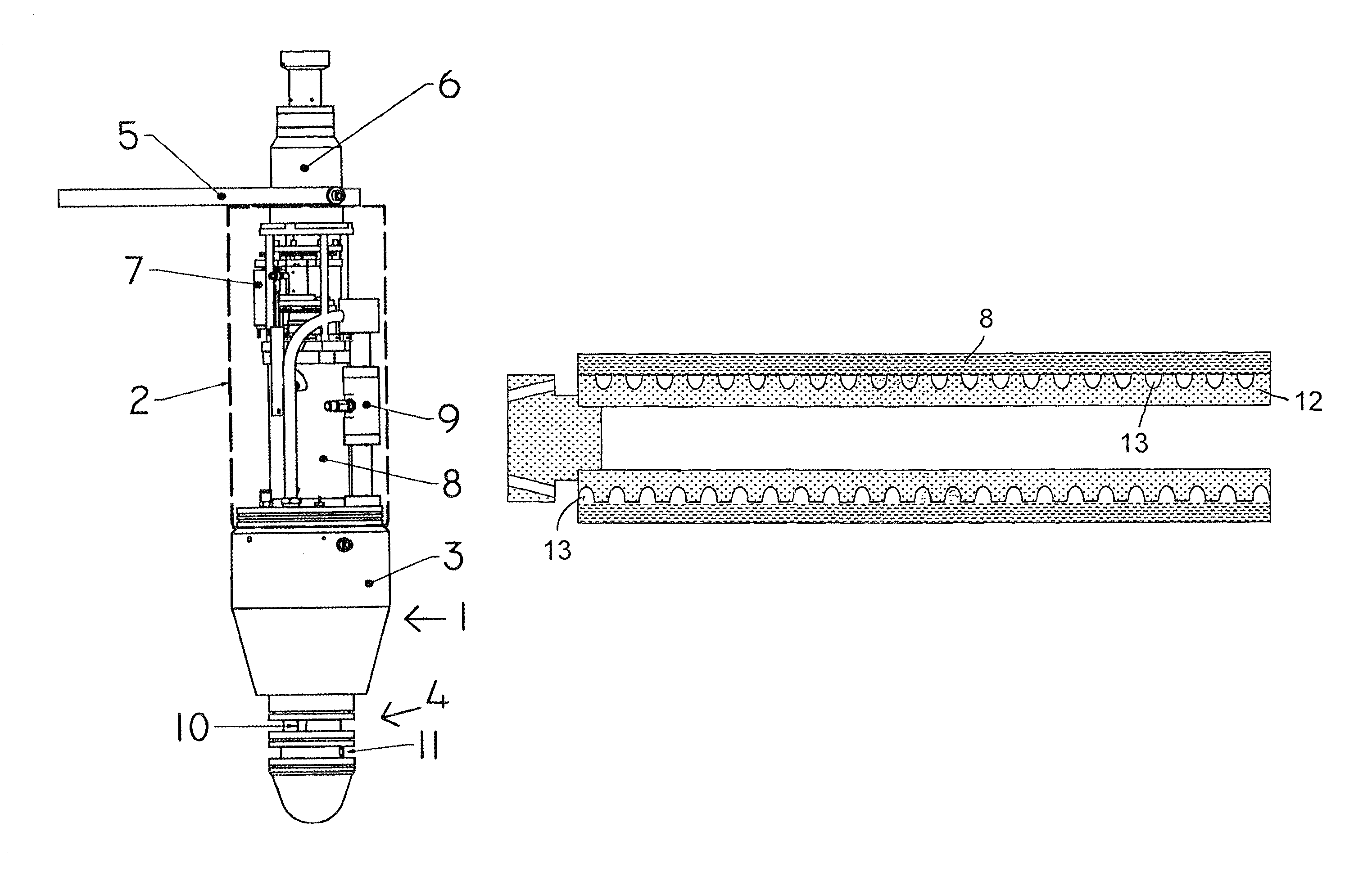
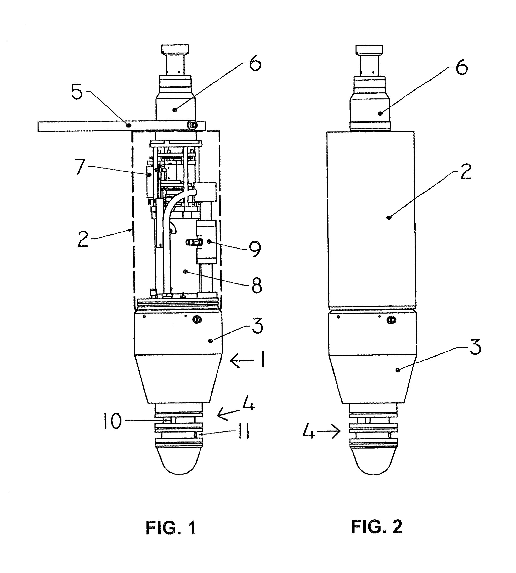
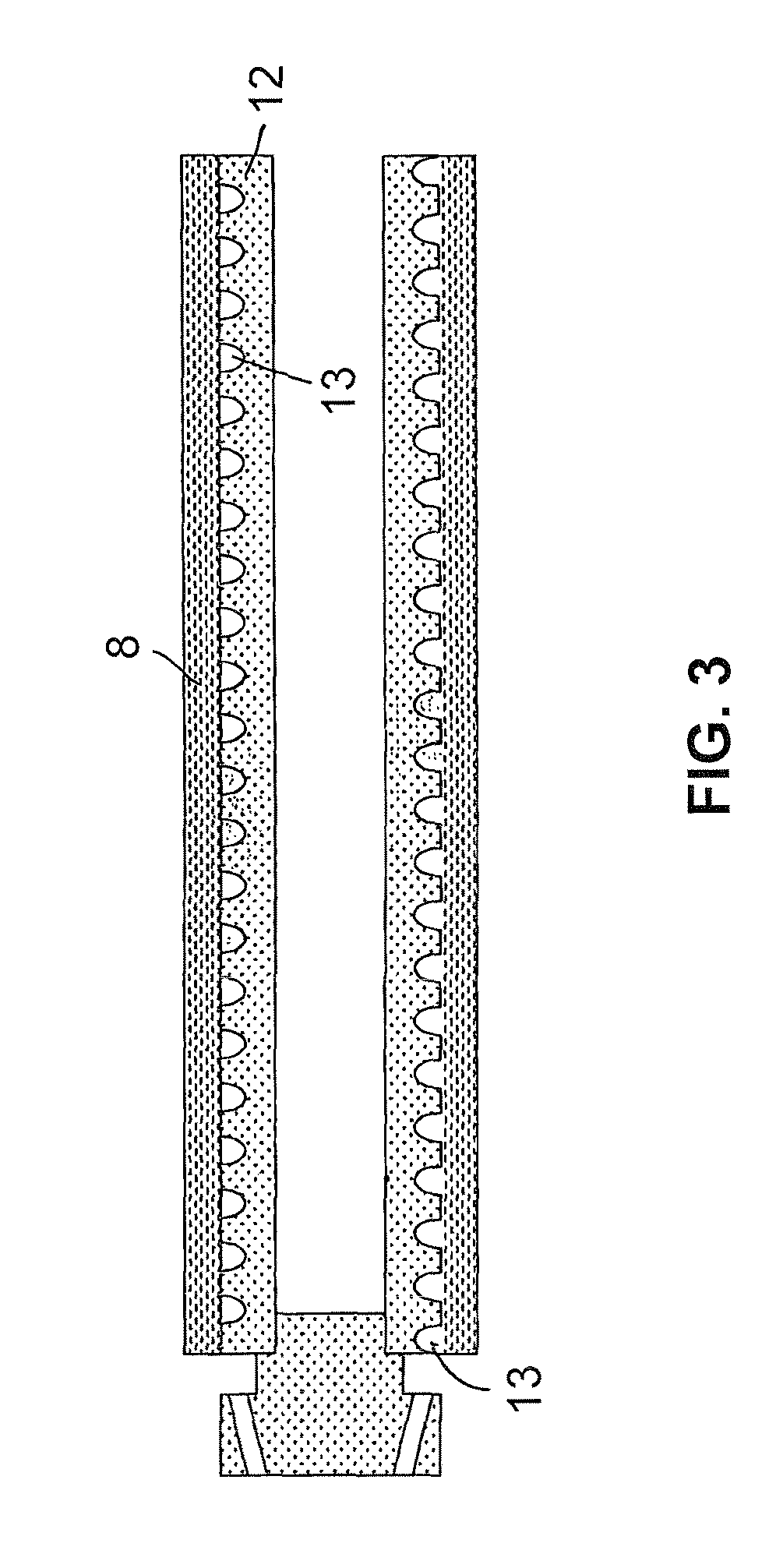
[0029]Reference is made to FIG. 1, illustrating an embodiment of a valve 1 according to the invention. The easily recognizable parts are an outer sleeve 2, a pipe section assembly 3, a stab end 4, a ROV handle 5 and an electrical assembly part 6. The outer sleeve 2 is partly transparent, indicating the internal parts electric motor 7 (means to adjust the axial position of the bolt within the pipe, by moving one or both of the bolt and pipe sections), a part of the outer surface of the pipe section 8, and also a turbine flow meter 9 is indicated. The stab end 4 includes an inlet port 10 and an outlet port 11. The parts are typically concentrically assembled along an axis, having the stab end 4 in front of a conically shaped pipe section assembly 3, which is in front of the means 7 to adjust the axial position of the bolt and pipe section, inside the outer sleeve 2, which again is in front of the ROV handle 5 and the electrical connector 6 (electrical assembly part).

[0030]FIG. 2 illus...


PUM


Abstract

Valve for throttling the flow rate of a fluid, distinguished in that it comprises a bolt (12), a pipe section (8) having inner dimension adapted to enclose the bolt sealingly, a groove (13) in at least one of the outer surface of the bolt and the inner surface of the pipe section, the groove providing a fluid passageway between the enclosed bolt and pipe section, an inlet port having fluid connection to an upstream end of the groove, an outlet port having fluid connection to a downstream end of the groove, and means to adjust a coaxial position of the bolt (12) relative to the pipe (8), by moving one or both of the bolt and pipe section, in order to adjust the throttling effect of the valve. System comprising valves of the invention.

Description

[0001]This application is the U.S. national phase of International Application No. PCT / EP2010 / 057063, filed 21 May 2010, which designated the U.S. and claims priority to Norway Application No. 2009 2006, filed 25 May 2009, the entire contents of each of which are hereby incorporated by reference.FIELD OF THE INVENTION[0002]The present invention relates to valves and devices for throttling a flow. More specifically, the invention relates to a valve for throttling a high-flow rate fluid, such as a hydrate inhibitor, and a system for injection flow throttling to a number of wells on a seabed.Background of the Invention and Prior Art[0003]Currently injection fluids are typically throttled or controlled by valves such as needle valves. This provides accuracy, however needle valves and other traditional control valves are susceptible to malfunction for several reasons. One typical reason for malfunction is clogging due to contamination by particles such as sand, another is mechanical wear...

Claims


Application Information

Patent Timeline
Patent Type & Authority Patents(United States)
IPC IPC(8): F16K47/06F16K47/12F16L55/027
CPCF16L55/02772F16K47/06F16K47/12
Inventor WIUM, ROLF
Owner ROXAR FLOW MEASUREMENT
Why Eureka
Try Eureka