Method for controlling wavelength-tunable laser

a wavelength-tunable laser and control method technology, applied in the direction of laser optical resonator construction, laser details, laser output parameters control, etc., can solve the problem of requiring a larger memory capacity, and achieve the effect of suppressing the memory capacity, and shortening the test tim

Active Publication Date: 2015-10-13
SUMITOMO ELECTRIC DEVICE INNOVATIONS
View PDF5 Cites 0 Cited by
  • Summary
  • Abstract
  • Description
  • Claims
  • Application Information

AI Technical Summary

Benefits of technology

[0007]It can be said that, in view of the problem mentioned above, for example, an object of the present invention is to provide a method for controlling a wavelength-tunable laser which can shorten the test time and suppress the memory capacity, for example.
[0008]The method for controlling a wavelength-tunable laser in accordance with one aspect of the present invention is a method for controlling a wavelength-tunable laser comprising a wavelength detection unit having an etalon, the method comprising a first step of acquiring a driving condition of the wavelength-tunable laser for laser oscillation at a first wavelength; a second step of calculating according to the driving condition of the first wavelength and a wavelength difference between the first wavelength and a second wavelength different from the first wavelength a control value or target value of a wavelength characteristic of the second wavelength in the wavelength detection unit, so as to calculate a driving condition for driving the wavelength-tunable laser; and a third step of feedback-controlling an oscillation wavelength according to a difference between a result of detection of a wavelength by the wavelength detection unit and the target value; the second step including a step of selecting according to the wavelength difference one of etalon slopes having respective gradients identical and opposite to a gradient of an etalon slope used for controlling the first wavelength. This method for controlling a wavelength-tunable laser in accordance with one aspect of the present invention can shorten the test time and suppress the memory capacity.
[0010]Another method for controlling a wavelength-tunable laser in accordance with one aspect of the present invention is a method for controlling a wavelength-tunable laser comprising a wavelength detection unit for detecting a wavelength by using a slope of any of a plurality of wavelength characteristics of an etalon, in which fundamental wavelengths are set in the slope on one side of the plurality of wavelength characteristics of the etalon, when a required wavelength is any of the fundamental wavelengths, a slope having a gradient identical to that of the fundamental wavelength is used for wavelength control, while, when the required wavelength differs from the fundamental wavelength, a slope having a gradient opposite to that of the fundamental wavelength is used for the wavelength control. This method for controlling a wavelength-tunable laser in accordance with one aspect of the present invention can shorten the test time and suppress the memory capacity.
[0011]Still another method for controlling a wavelength-tunable laser in accordance with one aspect of the present invention is a method for controlling a wavelength-tunable laser comprising a wavelength detection unit having an etalon, the method comprising a first step of acquiring from a memory a first driving condition for laser-oscillating the wavelength-tunable laser at a first wavelength; a second step of computing a second driving condition for oscillating the wavelength-tunable laser at a second wavelength with reference to the first driving condition and a wavelength difference between the first and second wavelengths; and a third step of detecting with the wavelength detection unit an output wavelength of the wavelength-tunable laser driven according to the second driving condition and performing according to a result thereof feedback control for correcting the driving conditions of the wavelength-tunable laser; the method further comprising a step, before the third step, of determining whether or not to reverse a correction sign for the correction in the feedback control with respect to a correction sign in the first driving condition. This method for controlling a wavelength-tunable laser in accordance with one aspect of the present invention can shorten the test time and suppress the memory capacity.
[0013]Yet another method for controlling a wavelength-tunable laser in accordance with one aspect of the present invention is a method for controlling a wavelength-tunable laser comprising a wavelength detection unit having an etalon with such a wavelength characteristic that signs of gradients of slopes reverse alternately, in which fundamental wavelengths are set in wavelength regions in one sign of the slopes, when one of the fundamental wavelengths is required, a driving condition for laser-oscillating the wavelength-tunable laser at the wavelength is acquired from a memory, an output wavelength of the wavelength-tunable laser driven according to the driving condition is detected by the wavelength detection unit, and according to a result thereof, feedback control for correcting the driving condition of the wavelength-tunable laser is performed, and when a wavelength in a wavelength region in the other sign of the slopes is required, a correction sign for the correction in the feedback control is reversed from the correction sign in the driving condition. This method for controlling a wavelength-tunable laser in accordance with one aspect of the present invention can shorten the test time and suppress the memory capacity.
[0014]The methods for correcting a wavelength of a wavelength-tunable laser in accordance with one aspect of the present invention can shorten the test time and suppress the memory capacity, for example.

Problems solved by technology

This necessitates an enormous amount of test time, thereby requiring a larger memory capacity as channel data increases.

Method used


Image

  • Method for controlling wavelength-tunable laser
  • Method for controlling wavelength-tunable laser
  • Method for controlling wavelength-tunable laser

Examples


first embodiment

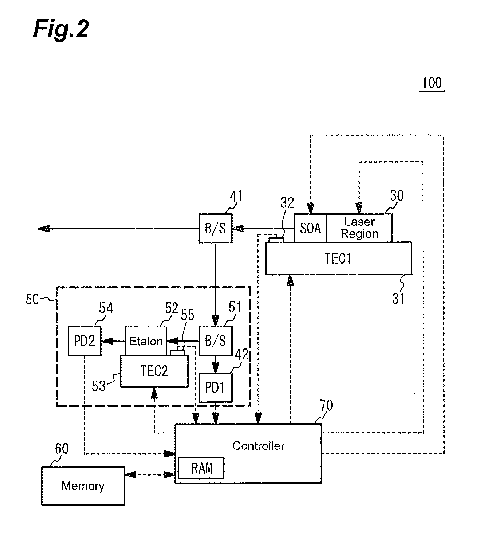
[0031]FIG. 2 is a block diagram illustrating an overall structure of a wavelength-tunable laser 100 in accordance with the first embodiment. As illustrated in FIG. 2, the wavelength-tunable laser 100 comprises, as a laser device, a semiconductor laser 30 (tunable semiconductor laser) which can control its wavelength. The semiconductor laser 30 in this embodiment is provided with a region to become an SOA (Semiconductor Optical Amplifier) by coupling with a laser region. The SOA functions as an optical output control unit. The SOA can arbitrarily increase and decrease the intensity of optical output. The SOA can also control the intensity of optical output so that it becomes substantially zero. The wavelength-tunable laser 100 further comprises an output detection unit 40, a wavelength locker unit 50, a memory 60, a controller 70, and the like. The controller 70 controls the wavelength-tunable laser 100 and has a RAM (Random Access Memory) therewithin

[0032]FIG. 3 is a schematic secti...

second embodiment

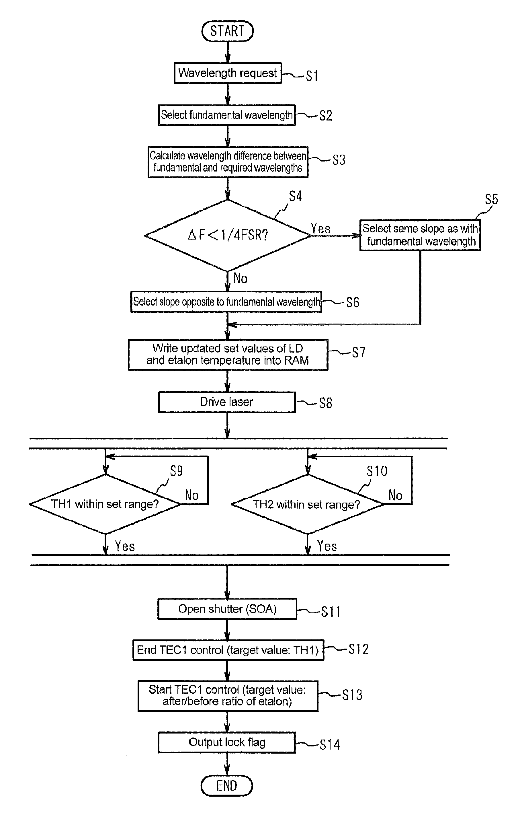
[0087]While the first embodiment explains arbitrarily set wavelength control (gridless control), the present invention is also applicable to grid control with fixed wavelengths. FIG. 10 is a flowchart for explaining a starting procedure for achieving a required wavelength (a given grid wavelength) of the semiconductor laser 30. As illustrated in FIG. 10, the controller 70 receives a wavelength request F′ (step S21). The required wavelength F′ is inputted from an external I / O device which is not depicted. Typically, an I / O device corresponding to the RS232C standard is employed. Subsequently, the controller 70 determines whether or not the required wavelength F′ is any of fundamental wavelengths F (step S22).

[0088]When it is determined “Yes” at step S22, the controller 70 selects the same slope as with the fundamental wavelength (step S23). When it is determined “No” at step S22, the controller 70 selects the slope opposite to the fundamental wavelength (step S24). After executing st...

modified example

[0095]The above-mentioned embodiment selects the slope. Selecting the slope is equivalent to selecting the sign for correcting the driving condition of the semiconductor laser 30 by feedback control in the auto frequency control. Hence, whether or not to reverse the sign for correcting the driving condition of the semiconductor laser 30 may be determined without selecting the slope.

[0096]FIG. 11 is a flowchart illustrating another example of the starting procedure for achieving the required wavelength of the semiconductor laser 30. Differences from the flowchart of FIG. 10 will be explained. When it is determined “Yes” at step S22, the controller 70 does not reverse the sign concerning the correction of the semiconductor laser 30 in the feedback control at step S31 (step S23′). Specifically, the controller 70 sets the fundamental wavelength flag. When it is determined “No” at step S22, the controller 70 reverses the sign concerning the correction of the semiconductor laser 30 in the...


PUM


Abstract

The method for controlling a wavelength-tunable laser comprises a first step of acquiring a driving condition of the wavelength-tunable laser for laser oscillation at a first wavelength, and a second step of calculating according to the driving condition of the first wavelength and a wavelength difference between the first wavelength and a second wavelength different from the first wavelength a control value or target value of a wavelength characteristic of the second wavelength in the wavelength detection unit, so as to calculate a driving condition for driving the wavelength-tunable laser, the second step including a step of selecting according to the wavelength difference one of etalon slopes having respective gradients identical and opposite to a gradient of an etalon slope used for controlling the first wavelength.

Description

BACKGROUND OF THE INVENTION[0001]1. Field of the Invention[0002]The present invention relates to a method for controlling a wavelength-tunable laser.[0003]2. Related Background Art[0004]Wavelength-tunable lasers which can select output wavelengths are disclosed (see, for example, Patent Literature 1). Such a wavelength-tunable laser is used for achieving an ITU-T grid, for example.[0005]Patent Literature 1: Japanese Patent Application Laid-Open No. 2009-026996SUMMARY OF THE INVENTION[0006]For achieving the ITU-T grid and the like, an etalon having transmission intensities at a predetermined wavelength interval is used. For achieving the ITU-T grid with a wavelength spacing of 50 GHz, for example, an etalon having an FSR (free spectral range) of 50 GHz is needed together with ITU-T information with a spacing of 25 GHz. This necessitates an enormous amount of test time, thereby requiring a larger memory capacity as channel data increases.[0007]It can be said that, in view of the probl...

Claims


Application Information

Patent Timeline
Patent Type & Authority Patents(United States)
IPC IPC(8): H01S3/13H01S5/024H01S5/0625H01S5/0687H01S5/068H01S5/343H01S5/06H01S5/12H01S5/026H01S5/028
CPCH01S5/06256H01S5/02407H01S5/02446H01S5/0687H01S5/06258H01S5/0265H01S5/34306H01S5/02438H01S5/0612H01S5/0617H01S5/06804H01S5/1209H01S5/1212H01S5/0287H01S5/02415H01S5/028
Inventor TANAKA, HIROKAZUSHIBATA, MASAOMIYATA, MITSUYOSHI
Owner SUMITOMO ELECTRIC DEVICE INNOVATIONS
Why Eureka
Try Eureka