Method of detecting a LED failure, a controller therefor, a lighting unit and lighting system

a technology of led failure and controller, applied in the direction of fault location, individual semiconductor device testing, instruments, etc., can solve the problems of incandescent light bulbs, the lifetime of led failures may be significantly longer, and the spread of lifetimes is not negligibl

Active Publication Date: 2015-10-13
NXP BV
View PDF9 Cites 7 Cited by
  • Summary
  • Abstract
  • Description
  • Claims
  • Application Information

AI Technical Summary

Benefits of technology

[0016]In embodiments the high current is such that the effect of a series resistance of an un-failed LED operating at the high current is to reduce the current by no more than 10% or 1%, compared with an idealised un-failed LED having zero series resistance.

Problems solved by technology

Moreover, LED lifetimes may be significantly longer than incandescent light bulbs.
Nonetheless, the spread of lifetimes is not negligible, and use LED strings, since a string is only as good as its worst LED.
In many applications this can lead to issues or challenges in applications which, it is therefore desirable or necessary to detect when a single LED in the string fails, in order that the system can react in a suitable way.
In applications where a string of different colour LEDs is used to provide a white light source—which may even be tuneable or dimmable—a failure of an LED would mean a shift in the total colour of the system; in other applications, in which each LED in a string of LEDs is separately visible—such as daytime running lights (DRL) in the automobile industry—there may be an aesthetic impact of the failure of a single LED.
Failure of an LED in a string of LEDs can generally occur in one of two ways: firstly, the LED may fail open-circuit in which case the entire string becomes open circuit, which is generally easy to detect; alternatively, the LED may fail in a closed-circuit mode.
Such a failure may not be so easy to detect.
So, for instance, it may not be possible to distinguish between a fully operational string of 20 LEDs each operating at a first junction temperature, and a string of 19 LEDs (together with one LED in which has failed in a short-circuit mode), at a second temperature 30° cooler than the first temperature.
Further, if the failure occurs during a start-up phase, there may not be a well-determined or stable forward voltage across the string, just prior to the failure, so it may not be possible to detect a change in the voltage, and an LED failure may thus go undetected.

Method used


Image

  • Method of detecting a LED failure, a controller therefor, a lighting unit and lighting system
  • Method of detecting a LED failure, a controller therefor, a lighting unit and lighting system
  • Method of detecting a LED failure, a controller therefor, a lighting unit and lighting system

Examples


Embodiment Construction

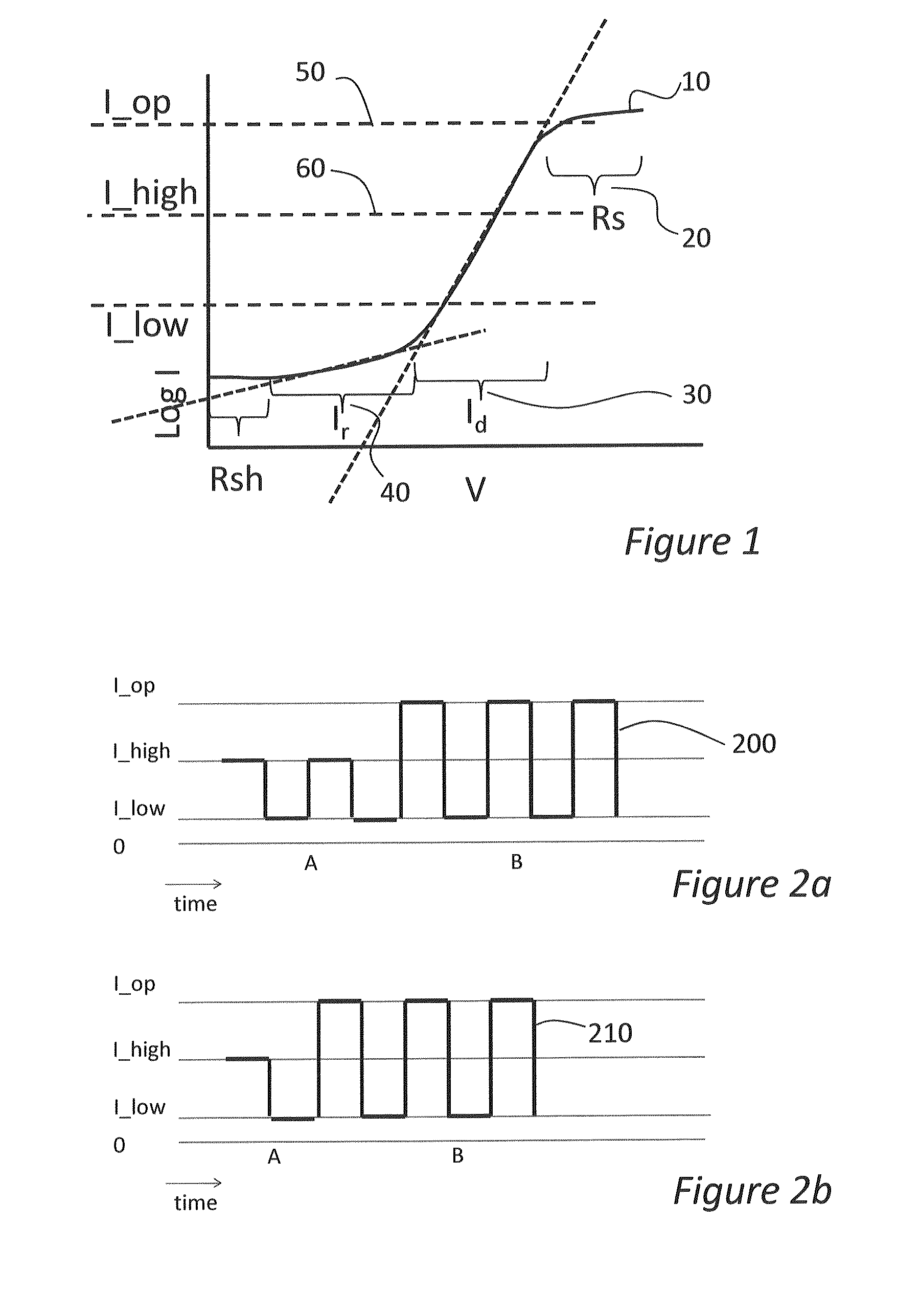
[0034]FIG. 1 shows a schematic of an I-V characteristic of a LED according to the classical two-diode model. According to this model, the DC I-V characteristic, that is to say the variation of forward voltage V with drive current I, of a LED, can be described through a combination of four components: series resistance Rs, shunt resistance Rsh, diffusion current Id, and recombination currents Ir, through:

I(V)=Id(V)+Ir(V)−V / Rsh′

or in more detail:

I=Id·eq / n1kT·(V-IRs)+Ir·eq / n2kT·(V-IRs)−(V−IRs) / Rsh.

As shown schematically in FIG. 1, the plot 10 of current, on the Y axis or ordinate, against voltage on the X axis or abscissa, has several separate regimes, in which respectively, the series resistance Rs, the diffusion current Id, the recombination current Ir component, or the shunt resistance Rsh, dominates. The dotted line in FIG. 1 with the steeper slope represents the exponential function for the diffusion current; the dotted line with the shallower slope represents the exponential func...


PUM


Abstract

Disclosed herein is a method of detecting an LED failure in a series-connected string of LEDs using a parameter indicative of a voltage difference between a voltage across the string at a predetermined relatively high current and a voltage across the string at a predetermined relatively low current. The disclosure extends to controllers configured to detect an LED failure in a string of LEDs, to LED lighting units comprising such controllers, and to lighting subsystems, for instance automobile lighting subsystems.

Description

CROSS-REFERENCE TO RELATED APPLICATIONS[0001]This application claims the priority under 35 U.S.C. §119 of European patent application no. 12187154.5, filed on Oct. 4, 2012, the contents of which are incorporated by reference herein.FIELD OF THE INVENTION[0002]This invention relates to methods of detecting an LED failure in a string of LEDs. It further relates to controllers configured to detect an LED failure in a string of LEDs, to LED lighting units comprising such controllers, and to lighting subsystems, for instance automobile lighting subsystems, which include one or more such LED lighting units.BACKGROUND OF THE INVENTION[0003]LEDs are used today as light sources for high performance lighting fixtures. There are known advantages of LEDs as a light source, such as high efficacy in terms of lumens per watt, small form factor and durability. Moreover, LED lifetimes may be significantly longer than incandescent light bulbs. For instance, it is reported that the average life time o...

Claims


Application Information

Patent Timeline
Patent Type & Authority Patents(United States)
IPC IPC(8): G01R31/00G01R31/26H05B33/08G01R31/08H05B44/00
CPCH05B33/0884H05B33/0893H05B33/089G01R31/2635H05B45/50H05B45/56H05B45/58
Inventor BRANCKEN, PASCALNGUYEN, VIET HOANGSURDEANU, RADU
Owner NXP BV
Why Eureka
Try Eureka