
Dual lumen cannula

a cannula and dual lumen technology, applied in the field of dual lumen cannulas, can solve the problems of increased risk of bleeding, increased risk of infection, pain and discomfort of patients, and patients with severe right ventricular failure, so as to reduce bleeding, pain and discomfort of patients, and increase the risk of vessel damage.

Active Publication Date: 2015-10-27
CARDIACASSIST
View PDF99 Cites 30 Cited by
  • Summary
  • Abstract
  • Description
  • Claims
  • Application Information

AI Technical Summary

Benefits of technology

The dual lumen cannula effectively reduces bleeding, vessel damage, and discomfort while enabling longer-term use and ambulatory access, improving right ventricular support and reducing mortality and morbidity by allowing direct blood flow management between the pulmonary artery and right atrium.

Problems solved by technology

Traditional cannulae used for patient life support generally involve single lumen cannulae at multiple insertion sites, high volume circuits, and cannulae that are not capable of long-term use.
Multiple insertion sites increase the risk of bleeding, vessel damage, infection, as well as pain and discomfort to the patient.
Patients with severe right-sided circulatory and / or right-sided ventricular failure have significantly high mortality and morbidity caused by a multitude of factors in multiple patient populations.
Surgically implanted LVADs can create a significant septal shift that leads to a dynamic change in the Starling curve that abruptly places patients into severe right ventricular failure.
Patients can limit post-transplant survival bridged to transplant to / from an RVAD with severe right ventricular failure.
The foregoing conventional devices do not have the capability to reach the pulmonary artery (PA) from the internal jugular vein via a percutaneous insertion.
In these embodiments, the patient's torso length can limit the ability to access the PA via percutaneous insertion.
If a cannula is not of a proper length, the interventional procedure may not unload the right ventricle, which leads to an increase of morbidity and mortality.
Therefore, residual blood is left stagnant in both the heart and lungs potentially leading to thrombosis and an inadequately unloaded right ventricle.
Additionally, the arterial cannulation can lead to problems including but not limited to bleeding, stroke, and infection.

Method used


Image

  • Dual lumen cannula
  • Dual lumen cannula
  • Dual lumen cannula

Examples


Embodiment Construction

[0028]For purposes of the description hereinafter, spatial orientation terms, if used, shall relate to the referenced embodiment as it is oriented in the accompanying drawing figures or otherwise described in the following detailed description. However, it is to be understood that the embodiments described hereinafter may assume many alternative variations and embodiments. It is also to be understood that the specific devices illustrated in the accompanying drawing figures and described herein are simply exemplary and should not be considered as limiting.

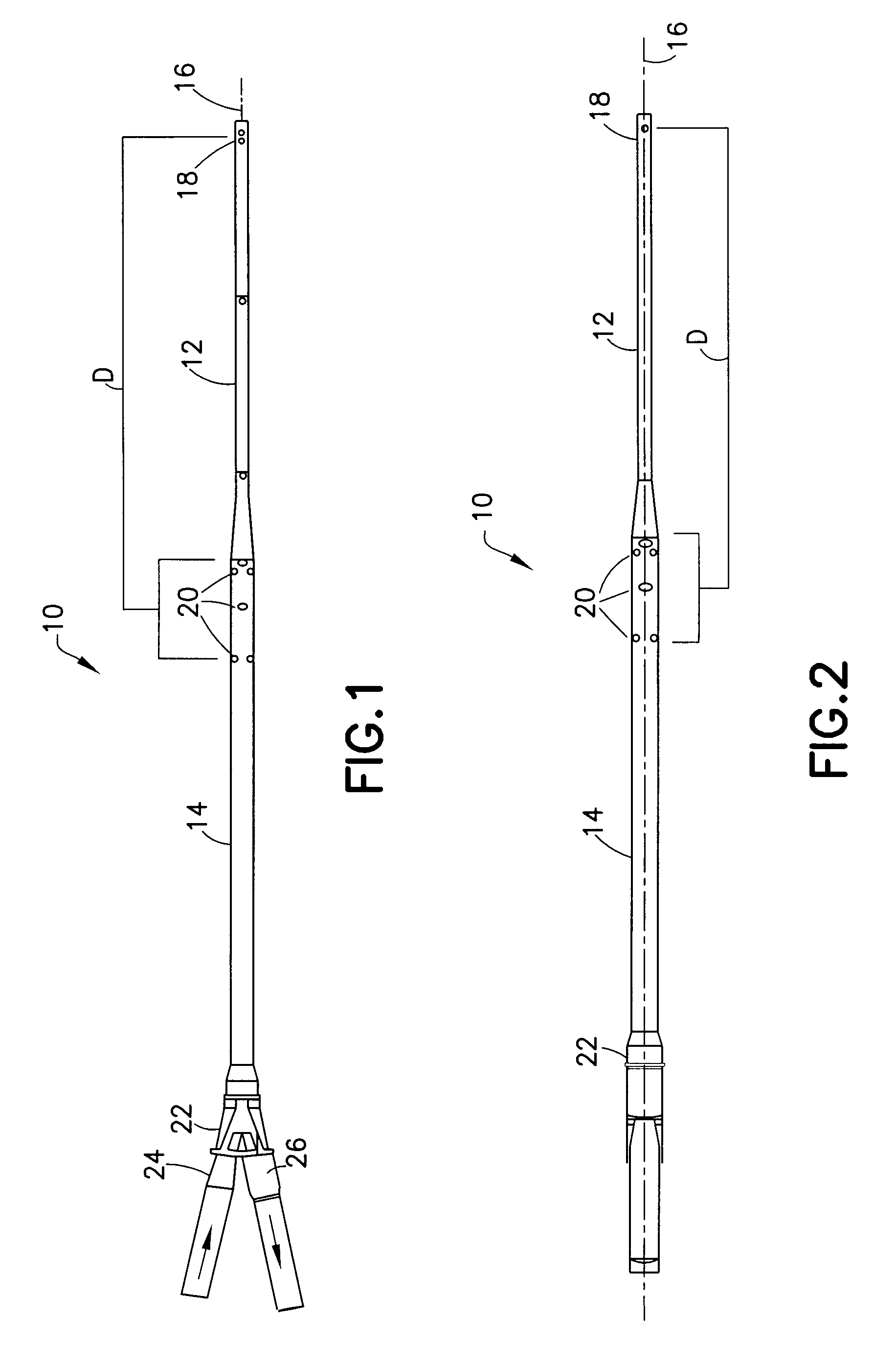
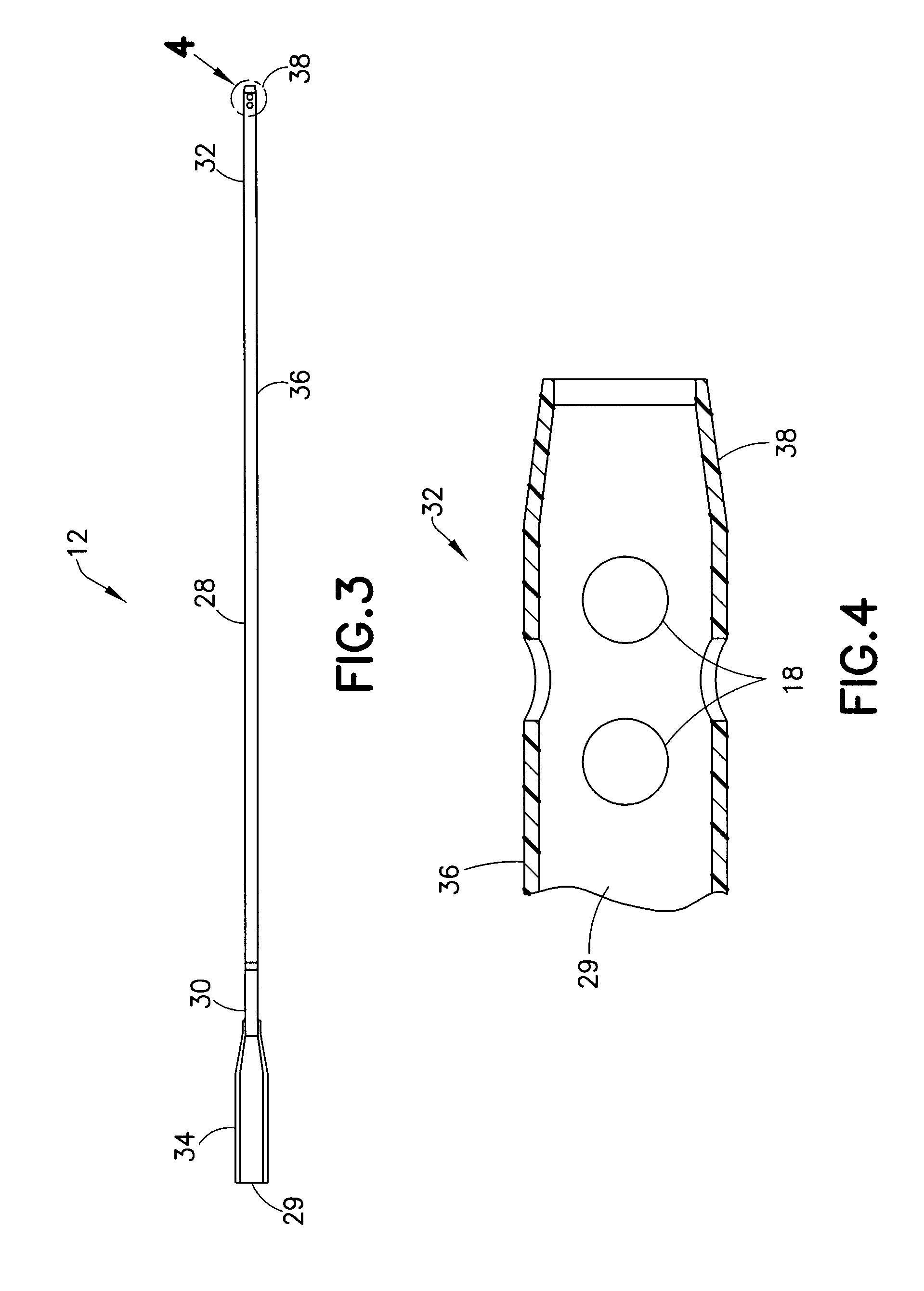
[0029]Referring to the drawings, in which like reference characters refer to like parts throughout the several views thereof, various embodiments of a coaxial, dual lumen cannula 10 (hereinafter referred to as “coaxial cannula 10”) are shown. With initial reference to FIGS. 1-2, the assembled coaxial cannula 10, according to one embodiment, generally includes a first infusion tube 12 having a first length and a second drainage tube ...


PUM


Abstract

A dual lumen coaxial cannula assembly includes a first infusion tube having a first elongate body defining a first lumen therethrough and a second drainage tube co-axially aligned with the first infusion tube and having a second elongate body with a second lumen defined by a space between the first infusion tube and second drainage tube. A connector is removably attached to the first infusion tube and the second drainage tube for coupling the dual lumen coaxial cannula to an extracorporeal blood circuit. The first infusion tube and the second drainage tube include a plurality of infusion and drainage apertures, respectively, provided at the distal end and extending through the sidewall of the first infusion tube and the drainage tube, respectively.

Description

CROSS-REFERENCE TO RELATED APPLICATIONS[0001]The present application claims priority to U.S. Provisional Patent Application No. 61 / 577,257, filed Dec. 19, 2011, entitled “Dual Lumen Cannula”, the entire disclosure of which is incorporated by reference herein.BACKGROUND OF THE INVENTION[0002]1. Field of the Invention[0003]The present invention relates, in general, to devices and methods for assisting a patient's heart with a cannula. More specifically, the present invention is related to devices and methods for assisting a patient's heart with a cannula where the cannula is of sufficient length to, for example, extend from the patient's internal jugular vein to the pulmonary artery.[0004]2. Description of the Related Art[0005]Traditional cannulae used for patient life support generally involve single lumen cannulae at multiple insertion sites, high volume circuits, and cannulae that are not capable of long-term use. Multiple insertion sites increase the risk of bleeding, vessel damag...

Claims


Application Information

Patent Timeline
Patent Type & Authority Patents(United States)
IPC IPC(8): A61M25/00A61M1/10A61M1/36A61M60/13A61M60/165A61M60/38A61M60/859
CPCA61M25/0026A61M1/10A61M1/3659A61M25/007A61M25/0029A61M25/005A61M2025/0031A61M2025/0039A61M60/113A61M60/38A61M60/13A61M60/859A61M60/165
Inventor KELLY, PATRICK A.LUTZ, PATRICK E.SVITEK, ROBERT G.STOKES, JERRY
Owner CARDIACASSIST
Learn More