Heat sink assembly for opto-electronic components and a method for producing the same

a technology of opto-electronic components and heat sinks, which is applied in the direction of lighting and heating apparatus, lighting and heating arrangements, electrical equipment, etc., can solve the problems of inability to use opto-electronic components such as leds with a maximum or even high power, and increase the use of leds instead of incandescent light bulbs, so as to achieve efficient conductivity to the luminaire structure, increase the ventilated surface area, and high thermal connection efficiency

Inactive Publication Date: 2015-11-03
LIGHTTHERM
View PDF25 Cites 6 Cited by
  • Summary
  • Abstract
  • Description
  • Claims
  • Application Information

AI Technical Summary

Benefits of technology

[0010]The object of the invention is achieved with a solution, in which thermally active inserts are embedded in an injection moulded plastic heat sink. Thermally active inserts are used for spreading the heat in effective way to heat dissipating injection moulded heat sink. Also electrically active inserts can be used for electrical connections between components. The inserts are preferably made of metal. The inserts have preferably surface areas which enable inter-metallic connection such as soldering or bonding. Such a contact has a good thermal and electrical conductivity.
[0054]“Thermally active insert” in this text means an insert which has a better thermal conductivity than the material of the heat sink it is embedded in, and which insert thus enhances heat distribution in the heat sink.

Problems solved by technology

Due to poor efficiency of incandescent lighting there is a tendency to increase the use of LEDs instead of incandescent light bulbs.
There are certain problems related to the prior art solutions for dissipating heat from electrical components such as LEDs.
The dissipation of heat is not efficient when the heat is conducted through several thermal interfaces between different parts, such as LED—MCPCB—heat sink, and interface materials in between, such as thermal interface materials like silicon grease between the MCPCB and heat sink.
Due to the inefficient heat dissipation the opto-electronic components, such as LEDs, cannot be used with a maximum or even with a high power.
Therefore, in order to achieve a certain power level, it is required to provide larger amount of opto-electronic components, which also adds to the production cost of a device.
The inefficient thermal connection limits also the integration density of LEDs, i.e. due to inefficient thermal connection LEDs close to each other start to heat up each other.
The more inefficient i.e. higher the thermal resistance of connection between the component and heat sink is, the smaller thermal resistance of the heat sink can be, which means relatively large heat sinks or active cooling.
In order to raise the emissivity it is beneficial to provide anodizing or other kind of coating for the metal heat sink, which causes costs.
The cost of the heat sink and MCPCB is relatively high compared to other components of a LED replacement bulb, for example.
A further disadvantage of the prior art assemblies relates to complicated production processes.
When the heat sink assembly includes a heat sink made of aluminium as well as a PCB the weight of the heat sink assembly tends to become high.
A typical LED replacement bulb solution assembled to a standardized lamp socket has a problem of providing poor and / or disturbed air flow for the heat sink of the replacement bulb.
Another air flow disturbing and heat dissipating surface minimizing factor is the volume that the power supply requires in the standardized socket LED replacement solutions.
This volume reservation reduces the volume available for arranging the heat dissipating surface.
Also, the standardized base is a closed structure, not allowing air to flow.
Another problem with the standard base / socket is poor conduction of heat through the base / socket to the luminaire structure.

Method used


Image

  • Heat sink assembly for opto-electronic components and a method for producing the same
  • Heat sink assembly for opto-electronic components and a method for producing the same
  • Heat sink assembly for opto-electronic components and a method for producing the same

Examples


Embodiment Construction

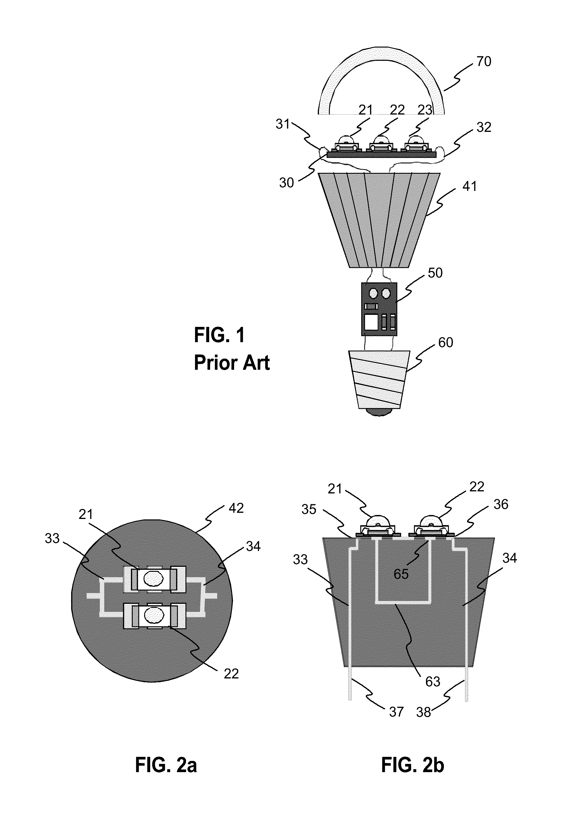
[0085]FIG. 1 was described in the prior art description above.

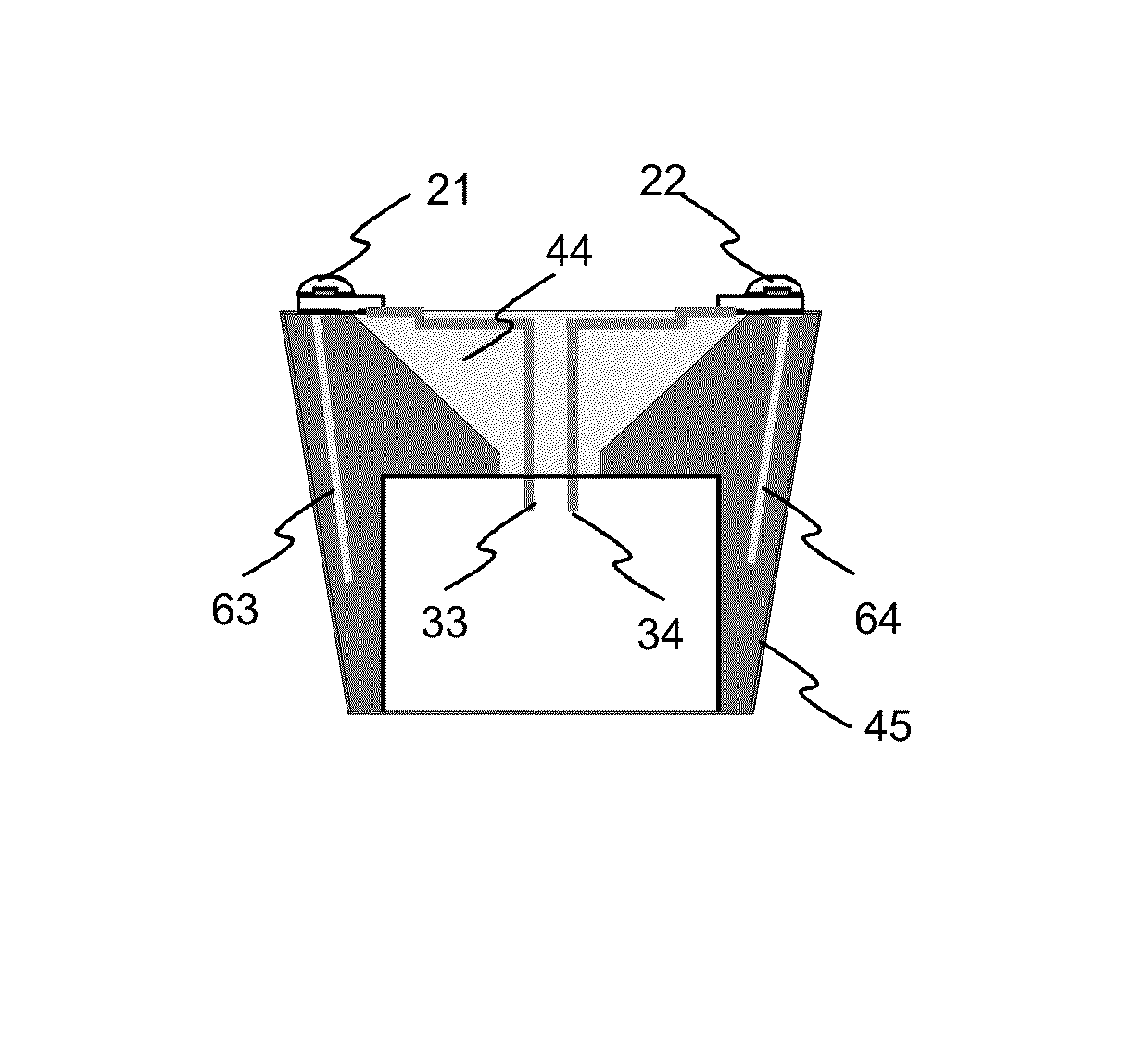
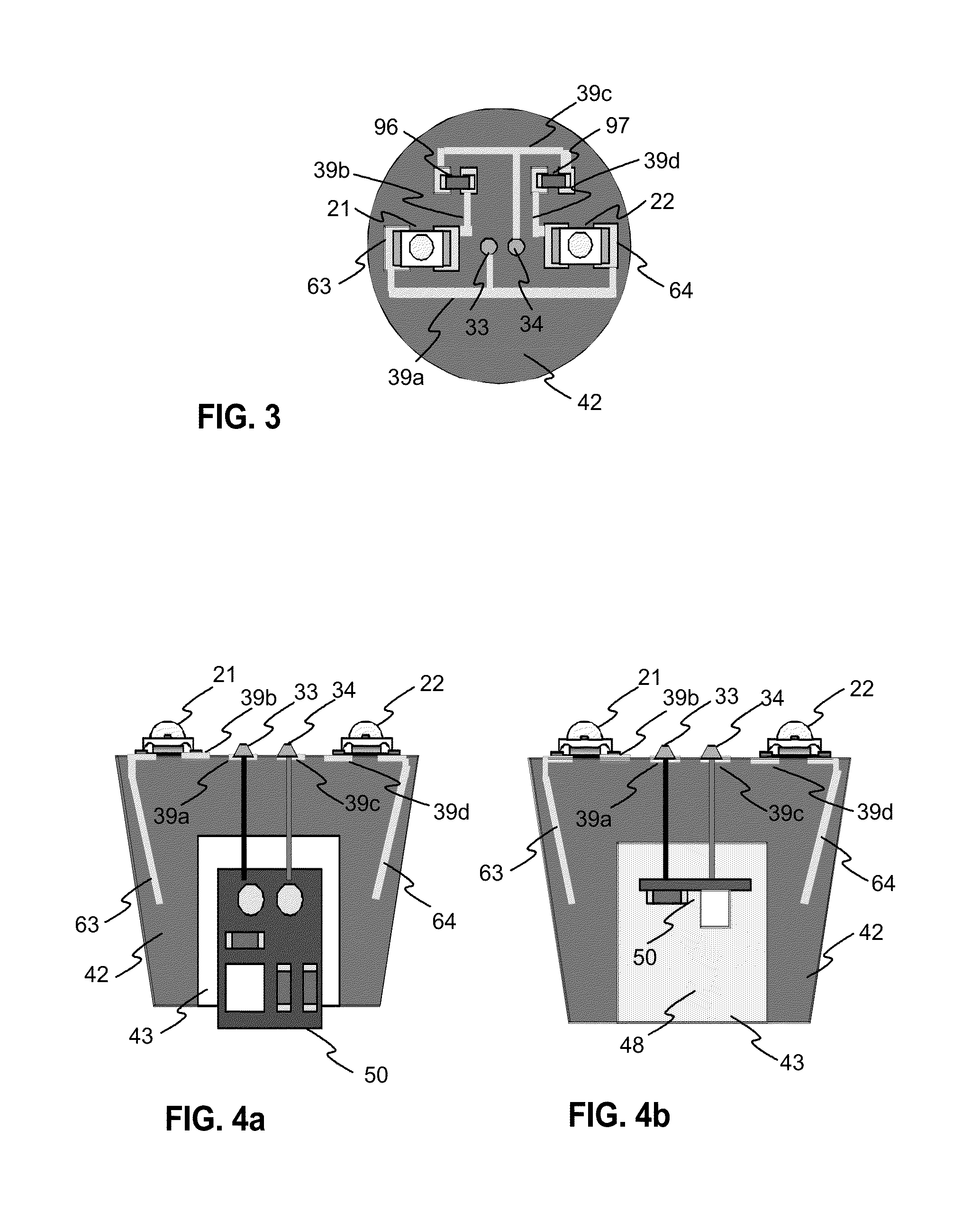
[0086]FIG. 2a illustrates top view of an exemplary heat sink assembly according to the invention. FIG. 2b illustrates a cross section view of a similar exemplary heat sink assembly according to the invention. The assembly has an injection moulded heat sink 42 with a planar surface at the top. The heat sink has embedded electrical inserts 33 and 34 and embedded thermally active insert 63, which have first exposed areas 35, 36 and 65 respectively at the top surface of the heat sink. There are two LEDs 21 and 22, which are electrically connected to the exposed areas of the inserts. The electrical contacts are connected to areas 35 and 36. However, the thermally active insert area 65 can also work as an electrical contact. At the opposite surface of the heat sink, the inserts have second exposed areas 37, 38, for the connection to a power supply PCB, for example. If the thermally active insert 63 is electrically active then i...


PUM

PropertyMeasurementUnit
poweraaaaaaaaaa
poweraaaaaaaaaa
emissivityaaaaaaaaaa

Abstract

The invention relates to a heat sink assembly and a method for producing the same. The invention can be applied, for example, in solid state lighting in order to improve the efficiency of heat dissipation. The object of the invention is achieved with a solution where effective thermal connection is provided from opto-electrical component in which thermally active inserts are embedded in an injection moulding to plastic heat sink. Solution of the invention can also provide also electrical connections for opto-electrical components.

Description

TECHNICAL FIELD[0001]The invention relates to a heat sink assembly for opto-electronic components and a method for producing the same. Moreover, the invention relates to the thermal management of such assembly. The invention can be applied in, for example, in solid state lighting in order to provide efficient heat dissipation.BACKGROUND TECHNOLOGY[0002]The invention is not limited to any certain applications, but as an example, we discuss the technology of LED replacement light bulbs. Due to poor efficiency of incandescent lighting there is a tendency to increase the use of LEDs instead of incandescent light bulbs. Incandescent light bulbs can be easily replaced by using LED replacement light bulbs. They are electrically and mechanically compatible with incandescent light bulbs but use less electrical energy for producing a certain luminous flux.[0003]FIG. 1 illustrates main parts of an exemplary prior art LED replacement light bulb. It has three LEDs 21, 22, 23, which are mounted o...

Claims


Application Information

Patent Timeline
Patent Type & Authority Patents(United States)
IPC IPC(8): F21V29/00F21V29/71F21V29/85F21V29/70F21Y101/02
CPCF21V29/70F21V29/713F21V29/85B29K2995/0013F21Y2101/02H01L2224/48091H01L2224/73265Y10T29/49117F21Y2115/10H01L2924/00014F21K99/00H01L33/641H01L33/642H01L33/64
Inventor JOKELAINEN, KIMMOMOILANEN, VILLERUPPRECHT, HOWARD
Owner LIGHTTHERM
Why Eureka
Try Eureka