
Graphene coating modified electrode plate for lithium secondary battery and method for producing the same

a lithium secondary battery and electrode plate technology, applied in the field of energy storage material technology, can solve the problems of providing very limited improvement on the performance of the battery and great difficulty in achieving a further breakthrough, and achieve excellent conductive properties

Active Publication Date: 2018-07-31
NINGBO INST OF MATERIALS TECH & ENG CHINESE ACADEMY OF SCI
View PDF29 Cites 0 Cited by
  • Summary
  • Abstract
  • Description
  • Claims
  • Application Information

AI Technical Summary

Benefits of technology

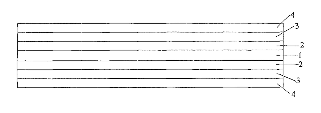
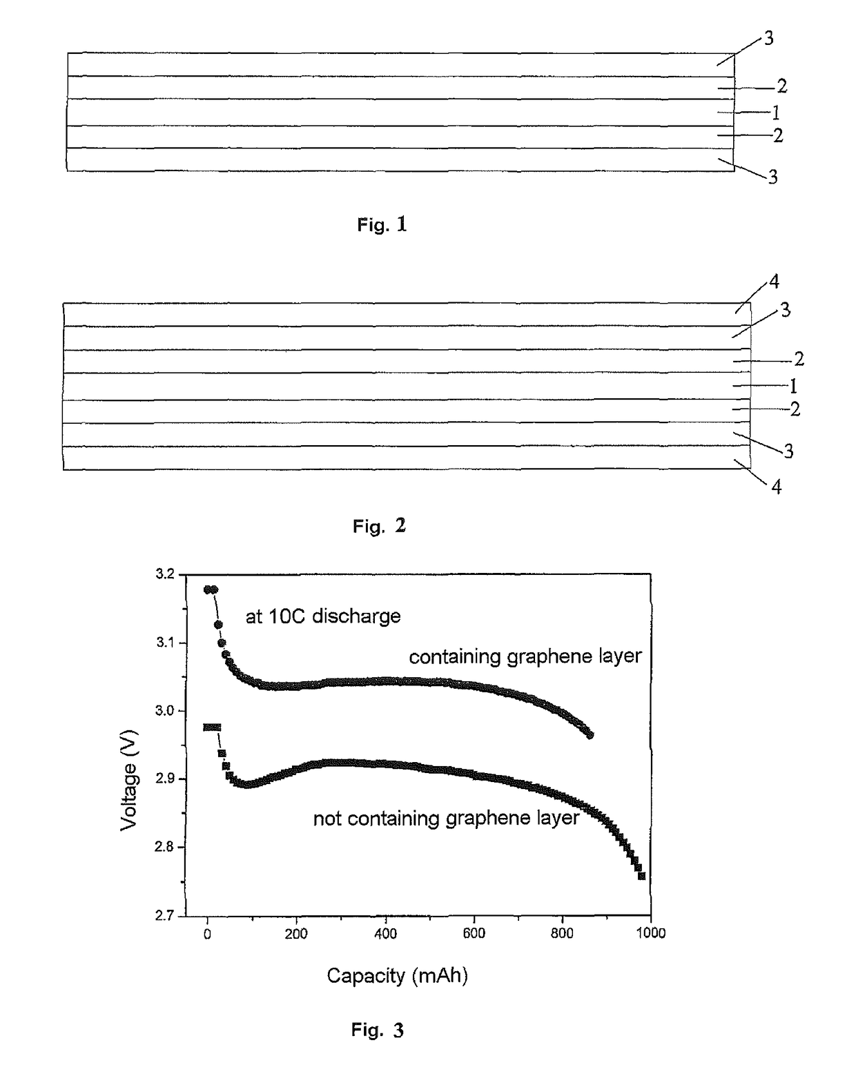
The present invention provides a graphene coating-modified electrode plate for lithium secondary battery, which has excellent conductive properties. The graphene layers coated on the current collector foil and the electrode active material layers coated on the graphene layers increase the electrode plate's electrical conductivity and dissipation functions due to the better electrical conductivity and thermal conductivity of graphene. Additionally, providing an extra graphene layer on the electrode active material layer improves the electrical conductivity. The power lithium-ion batteries produced using this electrode plate have superior high-power charge and discharge capacity as compared to the conventional batteries.

Problems solved by technology

Conventional methods for improving the performance of lithium power batteries include, such as, the use of new electrode active material, electrolyte, diaphragm, and the use of a wound battery core design or a laminated battery core design, which however provide very limited improvement on the performance of the batteries.
Accordingly, there is great difficulty in achieving a further breakthrough.

Method used


Image

  • Graphene coating modified electrode plate for lithium secondary battery and method for producing the same
  • Graphene coating modified electrode plate for lithium secondary battery and method for producing the same

Examples


example 1

Method for Producing the Electrode Plate

[0064]Graphene Layers Modified LiFePO4 Positive Electrode Plate

[0065](1) 70 parts by weight of graphene, 5 parts by weight of PVDF and 2000 parts by weight of NMP were sufficiently mixed and dissolved to obtain a slurry, the slurry was applied to both surfaces of an aluminum foil, and the coated foil was dried in an oven at 200° C. to obtain an aluminum foil modified with graphene layers. The thickness of the graphene layer on a single side was 3 microns (referred to as the inner graphene layer).

[0066](2) 90 parts by weight of LiFePO4, 5 parts by weight of PVDF, 5 parts by weight of SP and 200 parts by weight of NMP are sufficiently mixed and dissolved to obtain a slurry, the slurry was applied to both surfaces of the aluminum foil modified with graphene layers, and the coated foil was dried in an oven at 80° C. to obtain an electrode plate comprising positive material layers. The thickness of the positive material layer on a single side was 9...

example 2

Method for Producing the Electrode Plate

[0069]Graphene Layers Modified LiFePO4 Positive Electrode Plate

[0070](1) 98 parts by weight of graphene, 3 parts by weight of PVDF and 2500 parts by weight of NMP were sufficiently mixed and dissolved to obtain a slurry, the slurry was applied to both surfaces of an aluminum foil, and the coated foil was dried in an oven at 80° C. to obtain an aluminum foil modified with graphene layers. The thickness of the graphene layer on a single side was 3 microns.

[0071](2) 90 parts by weight of LiFePO4, 5 parts by weight of PVDF, 5 parts by weight of SP and 200 parts by weight of NMP were sufficiently mixed and dissolved to obtain a slurry, the slurry was applied to both surfaces of the aluminum foil modified with graphene layers, and the coated foil was dried in an oven at 80° C. to obtain an electrode plate comprising positive material layers. The thickness of the positive material layer on a single side was 90 microns.

[0072](3) 98 parts by weight of ...

example 3

Method for Producing the Electrode Plate

[0075]Graphene Layers Modified Graphite Negative Electrode Plate

[0076](1) 89 parts by weight of graphene, 2 parts by weight of PVDF and 2100 parts by weight of NMP were sufficiently mixed and dissolved to obtain a slurry, the slurry was applied to both surfaces of an copper foil, and the coated foil was dried in an oven at 120° C. to obtain a copper foil modified with graphene layers. The thickness of the graphene layer on a single side was 2 microns.

[0077](2) 92 parts by weight of graphite, 5 parts by weight of CMC, 3 parts by weight of KS-6 and 200 parts by weight of water were sufficiently mixed and dissolved to obtain a slurry, the slurry was applied to both surfaces of the copper foil modified with graphene layers, and the coated foil was dried in an oven at 110° C. to obtain an electrode plate comprising negative material layers. The thickness of the negative material layer on a single side was 90 microns;

[0078]The above obtained electro...


PUM

PropertyMeasurementUnit
thicknessaaaaaaaaaa
thicknessaaaaaaaaaa
thicknessaaaaaaaaaa

Abstract

The present invention provides a graphene coating-modified electrode plate for lithium secondary battery, characterized in that, the electrode plate comprises a current collector foil, graphene layers coated on both surfaces of the current collector foil, and electrode active material layers coated on the graphene layers. A graphene coating-modified electrode plate for lithium secondary battery according to the present invention comprises a current collector foil, graphene layers coated on both surfaces of the current collector foil, and electrode active material layers coated on the graphene layers. The graphene-modified electrode plate for lithium secondary battery thus obtained increases the electrical conductivity and dissipation functions of the electrode plate due to the better electrical conductivity and thermal conductivity of graphene. The present invention further provides a method for producing a graphene coating-modified electrode plate for lithium secondary battery.

Description

CROSS REFERENCE TO RELATED APPLICATIONS[0001]This is a U.S. national stage of application No. PCT / CN2011 / 081697, filed on 2 Nov. 2011. Priority under 35 U.S.C. § 119(a) and 35 U.S.C. § 365(b) is claimed from Chinese Application No. 201110123113.7, filed 12 May 2011, the disclosure of which are also incorporated herein by reference.FIELD OF THE INVENTION[0002]The present invention relates to a field of energy storage material technology, and more specifically relates to a graphene coating-modified electrode plate for lithium secondary battery.BACKGROUND ART[0003]With the depleting of traditional fossil fuels and increasing concern on environmental protection, demands for new green efficient energy becomes more and more urgent. The lithium-ion batteries, as a new energy source with a strong competitive advantage, draw extra attention. In addition to the widely application in the prior small and portable batteries, the development of lithium-ion batteries in high power and high energy ...

Claims


Application Information

Patent Timeline
Patent Type & Authority Patents(United States)
IPC IPC(8): H01M4/66H01M4/136H01M4/36H01M4/62H01M4/139H01M4/13H01M4/1397H01M10/052H01M4/04H01M4/02
CPCH01M4/136H01M4/0404H01M4/13H01M4/139H01M4/1397H01M4/622H01M4/625H01M4/663H01M4/667H01M10/052H01M4/366H01M2004/021Y02E60/10
Inventor LIU, ZHAOPINGTANG, CHANGLINZHANG, JIANGANGZHOU, XUFENGHU, HUASHENG
Owner NINGBO INST OF MATERIALS TECH & ENG CHINESE ACADEMY OF SCI
Learn More