Method of manufacturing a wind turbine blade comprising steel wire reinforced matrix material

a technology of reinforced matrix material and wind turbine blade, which is applied in the field of manufacturing methods, can solve the problems of time-consuming and tiresome process, difficult or impossible to avoid, and ensure the complete distribution of polymer in the entire mould cavity, and achieve the effect of short cycle tim

Active Publication Date: 2015-11-10
LM GLASSFIBER
View PDF9 Cites 12 Cited by
  • Summary
  • Abstract
  • Description
  • Claims
  • Application Information

AI Technical Summary

Benefits of technology

[0015]By using a comparatively high amount of steel wires, the overall time for supplying resin and curing can be substantially decreased due to the steel wires having a diameter or other inner dimension, which is substantially larger than that of glass fibres or carbon fibres, which are conventionally used in manufacturing of wind turbine blades. Due to the larger diameter of the wires, the voids are also larger, which in turn means that the liquid resin can propagate and impregnate the fibre reinforcement material at a faster rate. Thereby, the fibre material can be impregnated faster and consequently, the resin needs to be liquid for a shorter time, thus having the potential of decreasing the curing time also. Further, by using of metallic, electrically conducting wires, the blade wall itself may function as a lightning receptor and down conductor, thus alleviating the need for a separate lightning receptor and down conductor. Furthermore, the use of larger wires makes the use of high viscosity resin systems feasible. This is typically not possible when using glass fibres or carbon fibres due to the fine threads making impregnation with such resin impossible. This is particularly limiting within the field of thermoplastics. Also, due to the strength of metallic fibres, it is possible to manufacture a thinner shell, thus making it possible to lowering the impregnation time and subsequent curing time even further.
[0054]In-situ polymerisable thermoplastic materials, such as CBT, has the advantage that they obtain a water-like viscosity when heated to a temperature of approximately 150 degrees Celsius. Thereby, it is possible to quickly impregnate the fibre reinforcement material of very large composite structures to be moulded and subsequently curing the resin in very short cycle times.

Problems solved by technology

Ensuring a complete distribution of the polymer in the entire mould cavity is, however, often difficult, and accordingly this often results in so-called dry spots, i.e. areas with fibre material not being sufficiently impregnated with resin.
Thus dry spots are areas where the fibre material is not impregnated, and where there can be air pockets, which are difficult or impossible to avoid by controlling the vacuum pressure and a possible overpressure at the inlet side.
This is a time-consuming and tiresome process.
This is not desirable, especially not when the polymer has not hardened, as it can result in deformations in the inserted fibre material and thus in a local weakening of the structure, which can cause for instance buckling effects.
The disadvantage with prepregs is that the material cost is higher than for non-impregnated fibres.
Furthermore, the infusion process has become more complicated, as the impregnation of large shell members, such as blades, requires control of the flow fronts to avoid dry spots, said control may e.g. include a time-related control of inlet channels and vacuum channels.
This increases the time required for drawing in or injecting polymer.
As a result the polymer has to stay liquid for a longer time, normally also resulting in an increase in the curing time.

Method used


Image

  • Method of manufacturing a wind turbine blade comprising steel wire reinforced matrix material
  • Method of manufacturing a wind turbine blade comprising steel wire reinforced matrix material
  • Method of manufacturing a wind turbine blade comprising steel wire reinforced matrix material

Examples


second embodiment

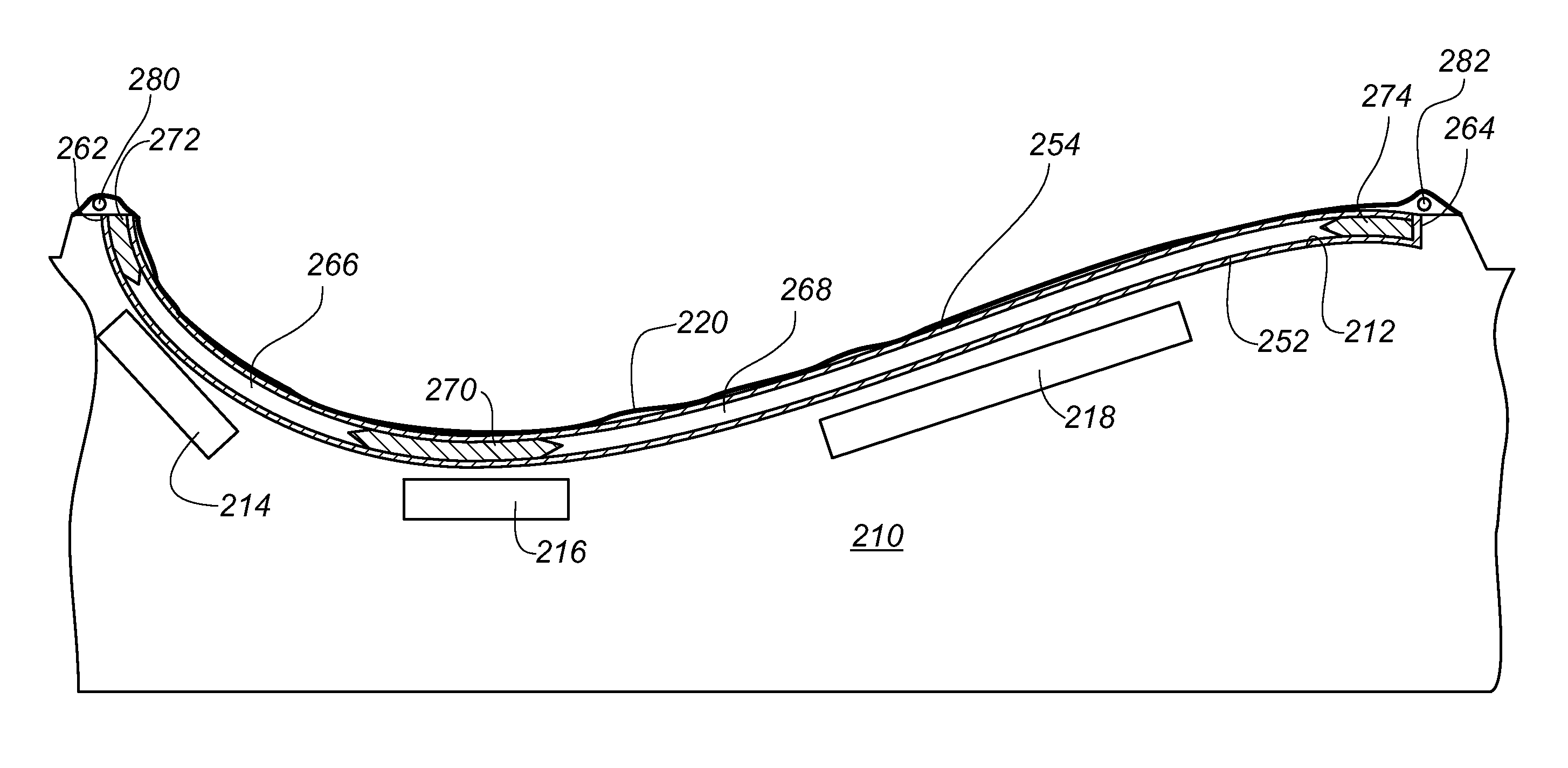
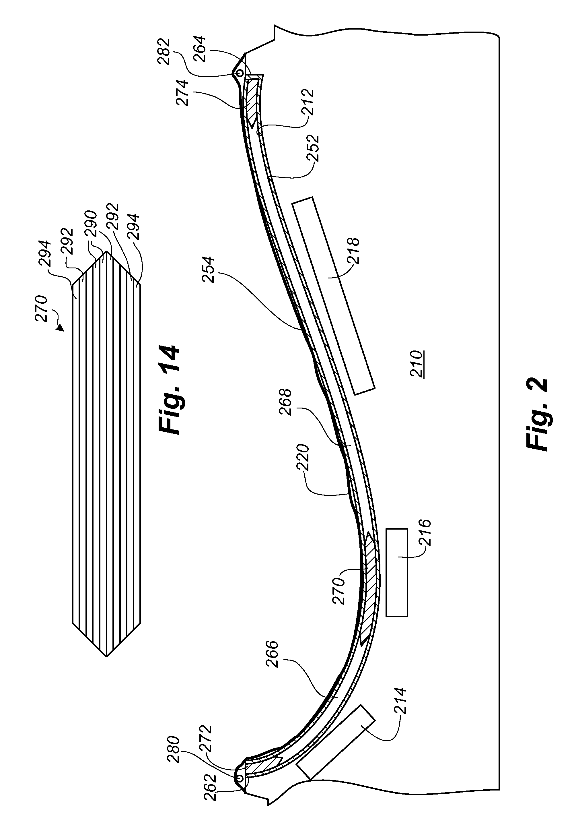
[0080]FIG. 2 shows a cross-sectional view through a first mould part 210 for use in a VARTM process. The mould part 210 comprises a mould cavity formed between a forming surface 212 and a vacuum bag 220, and in which a number of fibre layers, core parts and reinforcement sections are placed, these parts being included in a finished wind turbine blade shell part. The blade shell part comprises one or more lower fibre layers 252 impregnated with resin and optionally coated with a gelcoat, which define the exterior surface of the shell part, and one or more upper fibre layers 254 impregnated with resin, and which define the interior surface of the shell part. The upper fibre layer(s) 254 and lower fibre layer(s) 252 are separated by a fibre insertion or main laminate 270 comprising a plurality of fibre layers impregnated with resin, a first core part 266 and a second core part 268, as well as a first fibre reinforcement 274 at a trailing edge 264 of the shell part and a second fibre re...

first embodiment

[0083]Similar to the first embodiment, the first mould part 210 comprises magnet means in form of a number of electromagnets 214, 216, 218. The magnet means may be formed as a single electromagnet along the forming surface 212 or may comprise a plurality of electromagnets 214, 216, 218 as shown in the figure. The electromagnets can be used to retain or secure the fibre layers 252, 254, 256 against the forming surface 212 during the process of arranging the fibre layers 252, 254, 256 in the mould cavity and / or the evacuation process and / or the following impregnation process.

[0084]Particularly the process of impregnating the main laminate 270 and other fibre reinforcements is very time consuming. Therefore, the change from using reinforcement sections comprising mainly glass or carbon fibres to reinforcement sections comprising a majority, and preferably more than 80% by volume of steel wires, reduces the overall impregnation time substantially, and thereby the overall time for manufa...

third embodiment

[0085]FIG. 3 shows a cross-sectional view through a first mould part 310 for use in a VARTM process, and in which like numerals refer to similar parts shown in FIG. 1. Therefore, only the difference between the embodiments is described.

[0086]In this embodiment a number of prepregs 392 and / or pre-cured elements comprising metallic wires, preferably steel wires, are arranged between a number of outer fibre layers 354 and a number of inner fibre layers 352, optionally coated with a gelcoat, which define a part of the exterior surface of the blade shell part. The prepregs are pre-impregnated with resin, and the mould cavity is heated to a temperature, where the resin is allowed to reflow thus filling the mould cavity and the fibre material arranged therein. The heating eventually allows the resin to cure.

[0087]Again, the outer fibre layers 352 may be made of fibres having a diameter substantially smaller than that of the steel wires in the prepregs 392. The outer fibre layers 352, 354 m...


PUM

PropertyMeasurementUnit
lengthaaaaaaaaaa
lengthaaaaaaaaaa
lengthaaaaaaaaaa

Abstract

A method of manufacturing a shell construction part of a wind turbine blade, the shell construction part being made of a fibre reinforced polymer material including a polymer matrix and fibre reinforcement material embedded in the polymer matrix. The method comprises the steps of a) providing a forming structure comprising a mould cavity and having a longitudinal direction, b) placing the fibre reinforcement material in mould cavity, c) providing a resin in the mould cavity simultaneously with and / or subsequently to step b), and d) curing the resin in order to form the composite structure, wherein at least 20% by volume of the fibre reinforcement material consists of metallic wires.

Description

[0001]This is a National Phase Application filed under 35 U.S.C. 371 as a national stage of PCT / EP2009 / 060547, filed Aug. 14, 2009, an application claiming the benefit from the European patent Application No. 08014496.7, filed Aug. 14, 2008the content of each of which is hereby incorporated by reference in its enitirety.TECHNICAL FIELD[0002]The present invention relates to a wind turbine blade including a shell structure made of a fibre reinforced polymer material including a polymer matrix and fibre reinforcement material embedded in the polymer matrix. The invention further relates to a method of manufacturing a shell construction part of a wind turbine blade, the shell construction part being made of a fibre reinforced polymer material including a polymer matrix and fibre reinforcement material embedded in the polymer matrix.BACKGROUND[0003]Vacuum infusion or VARTM (vacuum assisted resin transfer moulding) is one method, which is typically employed for manufacturing composite str...

Claims


Application Information

Patent Timeline
Patent Type & Authority Patents(United States)
IPC IPC(8): F03D1/06B29C70/88B29C70/44B29C33/12B29L31/08
CPCF03D1/065B29C33/12B29C70/44B29C70/885B29L2031/085Y02E10/721Y02E10/72Y02P70/50
Inventor GRABAU, PETER
Owner LM GLASSFIBER
Why Eureka
Try Eureka