Method and apparatus for positioning heating elements

a heating element and positioning technology, applied in the field of underlayments, can solve the problems of poor heat dissipation effect, and inability to maintain hot water storage tanks, so as to facilitate the placement of the same, reduce the weight of the underlayment layer, and enhance the bond

Active Publication Date: 2015-11-17
PROGRESS PROFILES
View PDF72 Cites 53 Cited by
  • Summary
  • Abstract
  • Description
  • Claims
  • Application Information

AI Technical Summary

Benefits of technology

[0008]It is another aspect of the present invention to provide an underlayment layer that facilitates bonding of successive flooring layers. More specifically, the base of one embodiment of the present invention includes at least one opening that allows adhesive applied above and below the underlayment layer to communicate. “Adhesive” as used herein shall mean thin set, mortar, grout, self-leveling underlayment, etc. Adhesives are used to firmly associate the underlayment layer with a subfloor, wherein a layer of adhesive is initially applied to the subfloor with the underlayment layer placed thereon. Some embodiments of the present invention include a base with a roughened contact surface or that is associated with a wire or plastic mesh material to help facilitate the bond between the underlayment layer and the layer of adhesive. Next, the plurality of heating elements is associated with the bosses of the underlayment layer. Once the predetermined wire configuration is achieved, a second adhesive layer is placed atop of the underlayment layer and associated wires, which fills the spaces between adjacent bosses. Grout or other adhesives are then placed atop of the second layer of adhesive that is adapted to receive tiles, wood flooring etc. In one embodiment of the present invention, the base includes at least one opening therethrough to allow the first layer of adhesive to interact with the second layer of adhesive, thus providing a continuous adhesion path through the thickness of the underlayment layer.
[0009]The opening (and holes described below) may also allow water to flow through the underlayment layer. More specifically, often in floor heating systems are used in outdoor environments. The openings in the bosses and the base may thus be used to allow water flow from the floor through the subfloor to a catch basin or a drainage system. The openings also allow for air to percolate through the floor during fabrication, which helps some types of adhesive cure.
[0010]In a related aspect of the present invention, embodiments employ a boss having an opening therethrough. That is, some bosses of the present invention are ring shaped having an inner diameter and an outer diameter. The inner diameter may also be associated with an opening in the base such that the second layer of adhesive may be located within the boss to communicate with the first layer of adhesive which also creates an enhanced bond between the first layer of adhesive and the second layer of adhesive. Bosses of some embodiments of the present invention are also at least partially hollow with a plurality of holes associated with an upper surface thereof. The hollow bosses decrease the weight of the underlayment layer which facilitates placement of the same. In addition, material savings are appreciated by using hollow bosses. Hollow bosses may in one embodiment receive a first layer of adhesive such that the second layer of adhesive communicates with the first layer of adhesive through the plurality of holes. Other embodiments of the present invention omit such holes and provide an airtight or at least semi airtight volume of air that is heated by the heating elements to help regulate the heat being emanated by the floor.
[0011]It is another aspect of the present invention to provide spacing between adjacent bosses that is uniquely suited to the diameter or shape of the heating element to help firmly secure the same. In addition, some embodiments of the present invention employ bosses that are non-rigid and somewhat compliant that flex to receive the heating element. This interference or frictional fit between heating element and boss helps secure and protect the heating elements.
[0012]It is another aspect of the present invention to provide an underlayment layer with at least one boss that helps facilitate the remaining construction of the floor. More specifically, some embodiments of the present invention include bosses with upwardly projecting protrusions that act as guides to help the finisher ascertain the amount of adhesive or grout needed to bring the floor up to a predetermined grade. It is contemplated that such protrusions be used to place grout atop the bosses wherein top surfaces of the protrusions remain uncovered by the grout to define the finished grade. This will allow the finisher to be confident that the grout is at the desired level without having to make many measurements.
[0013]It is another aspect of the present invention to provide bosses having an outwardly protruding lip. More specifically, in one embodiment, the upper portion of the boss side surface, which will be shown in greater detail below, may be comprised of a continuous surface or at least one tab that ultimately is positioned in the space between adjacent bosses. Preferably, the tab is resiliently deflectable such that the heating element may be placed between adjacent bosses by flexing the same. Thereafter, the surface or tab will help maintain the position of the heating element between two adjacent bosses.

Problems solved by technology

The size of tubes generally translates into a thicker floor, which may be undesirable.
One other disadvantage of a hydronic system is that a hot water storage tank must be maintained at all times, which is less efficient than an electric floor heating system.
The wire of Fuhrman, however, is not secured between adjacent studs and still may separate therefrom, which may cause uneven heating or wire damage.
Furthermore, Fuhrman discloses a continuous mat wherein subsequent layers of adhesive are not able to interact with those previously placed.

Method used


Image

  • Method and apparatus for positioning heating elements
  • Method and apparatus for positioning heating elements
  • Method and apparatus for positioning heating elements

Examples


Embodiment Construction

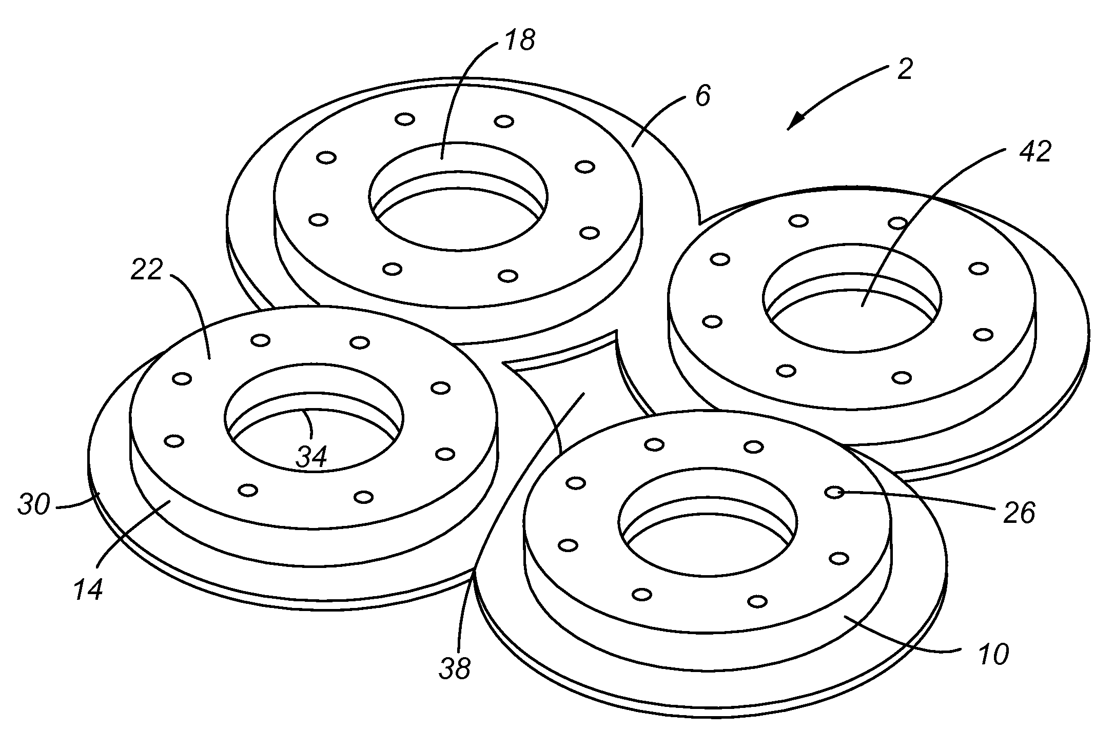
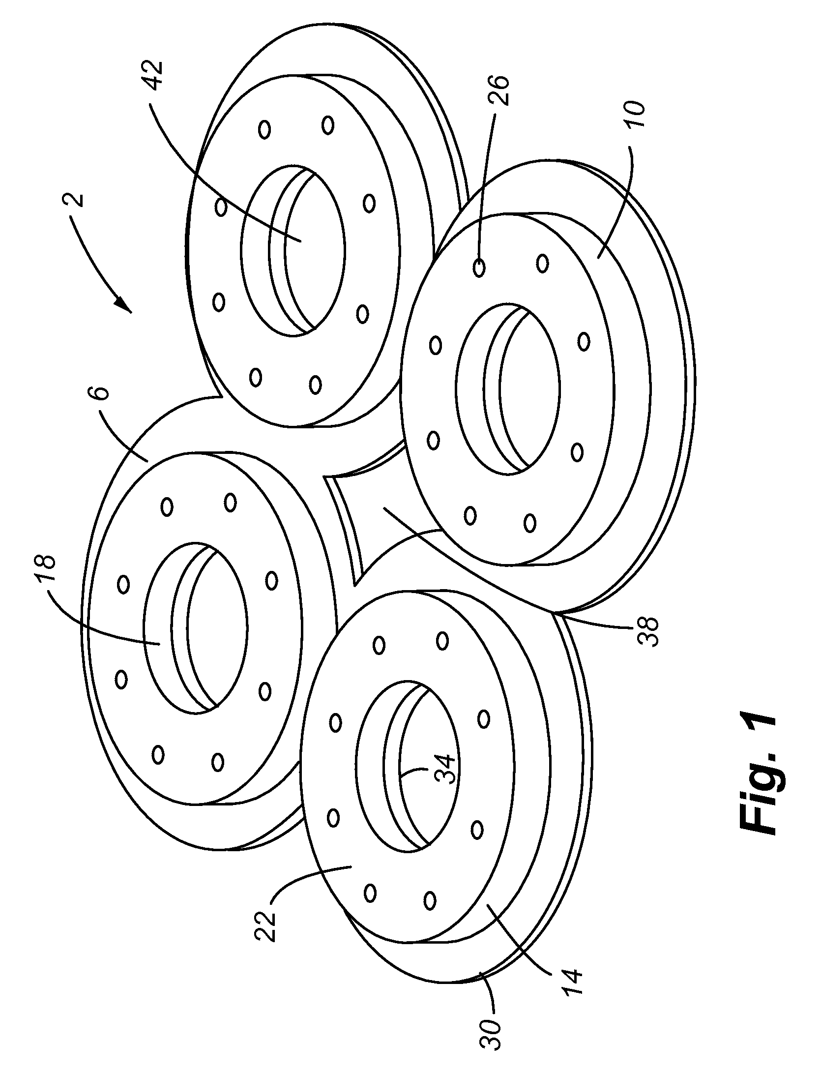
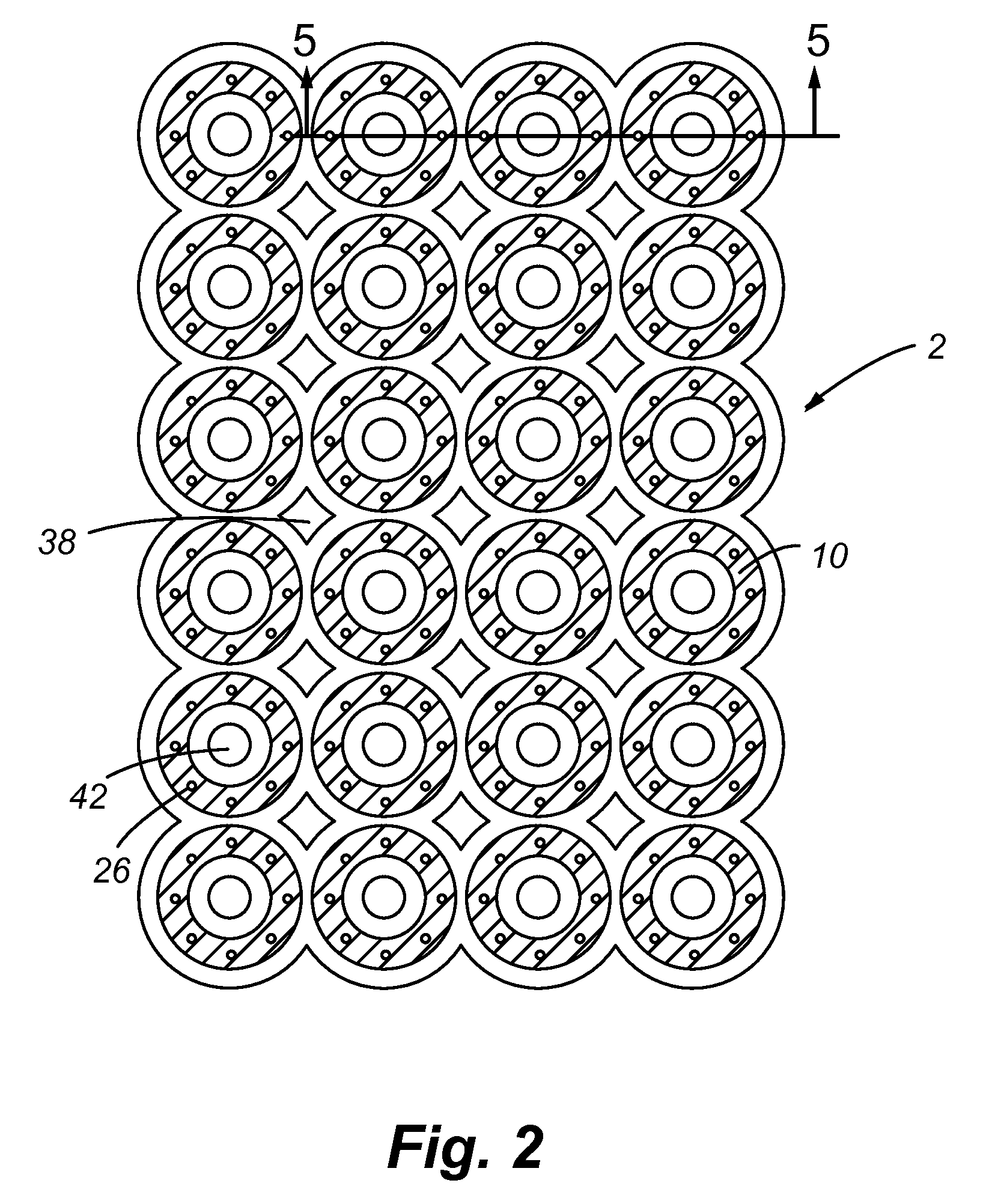
[0033]Referring now to FIGS. 1-5, an underlayment layer 2 of one embodiment of the present invention is shown that includes a system of interconnected bases 6 and bosses 10. That is, preferably, each base 6 includes a boss 10 extending therefrom. Each boss 10 includes an outer surface 14 and an inner surface 18 and an upper surface 22. In some embodiments the upper surface 22 includes a plurality of holes 26. The bases 6 are generally circular and the bosses 10 are generally cylindrical. The bases 6 also include an outer diameter 30 and inner diameter 34. Again, a plurality of base / boss combinations are interconnected to form the underlayment layer 2.

[0034]The bosses 10 of one embodiment of the present invention are between about 1 / 16 inches wide. The spacing between individual bosses 10 is between about 1 inch to 1.5 inches. One skilled in the art, however, will appreciate that the boss sizes and spacing therebetween may be altered to accommodate different sizes of heating elements...


PUM


Abstract

An underlayment system is provided that includes a plurality of bosses that emanate from a common base member. The bosses and bases preferably include an opening therethrough that will allow for subsequent layers of adhesive to interact and bond to each other. The bosses are also spaced in such a way to help secure a wire snugly therebetween.

Description

FIELD OF THE INVENTION[0001]Embodiments of the present invention are generally related to underlayments associated with radiant floor or wall heating systems. More specifically, one embodiment of the present invention includes a plurality of protrusions that are adapted to locate and firmly secure wires or pipes associated with a radiant heating system.BACKGROUND OF THE INVENTION[0002]In-floor and in-wall heating and cooling is well known that utilizes heat conduction and radiant heat, for example, for indoor climate control rather than forced air heating that relies on convection. The heat is usually generated by a series of pipes that circulate heated water or by electric cable, mesh or film that provide heat when a current is applied thereto. In-floor radiant heating technology is used commonly in homes and businesses today.[0003]Electrical floor heating systems have very low installation costs and are well suited for kitchens, bathrooms or in rooms that require additional heat, ...

Claims


Application Information

Patent Timeline
Patent Type & Authority Patents(United States)
IPC IPC(8): F24D3/14F24D3/16F24D13/02E04B5/48
CPCF24D13/024F24D3/144Y02B30/26F24D3/141Y02B30/00E04B5/48F16L3/02E04F15/182E04F15/185E04F2290/023
Inventor LARSON, DAVID D.
Owner PROGRESS PROFILES
Why Eureka
Try Eureka