Control of a wind turbine, rotor blade and wind turbine

a technology of rotor blades and wind turbines, which is applied in the direction of machines/engines, liquid fuel engines, transportation and packaging, etc., can solve the problems of rotor blades that are easily damaged, etc., to prolong the service life of the wind turbine system, reduce inverse stresses, and reduce particularly strong stresses

Inactive Publication Date: 2015-11-24
SIEMENS AG
View PDF11 Cites 13 Cited by
  • Summary
  • Abstract
  • Description
  • Claims
  • Application Information

AI Technical Summary

Benefits of technology

[0010]It may be desirable to avoid the afore-cited disadvantages and create an efficient solution in order to reduce particularly strong stresses on the wind turbine and / or its rotor blades and to reduce inverse stresses and thus to extend the service life of the wind turbine system and / or reduce maintenance costs.

Problems solved by technology

High stresses in the form of deflections of the rotor blades are herewith unwanted, particularly if states with a high stress alternate in real-time with states without stress or even with states with inverse stress (dynamic alternating stresses).
For instance, alternating deflections due to excitation with a resonance frequency or on account of the alternating wind speeds as a function of the position of the rotor blade result in particularly significant weathering of the rotor blade.
A rotor blade of a wind turbine must typically withstand millions of stress cycles, which result in gradual wear of the rotor blade and reduce the remaining service life.
It is herewith disadvantageous if the afore-cited particularly strong stresses drastically shorten the service life of the wind turbine.
This results in a change in the output produced by the wind turbine.
However, the imminent stress on the rotor blade is not known in advance and a tilting of the rotor blade, which has a weight of 10 tonnes or more for instance, requires energy and time.
In addition, it is disadvantageous that such an adjustment of the rotor bade itself effects a considerable stress on and wear associated therewith of the bearing of the rotor blade and the tilting actuators, which in turn has a negative effect on the service life of the system and on the necessary maintenance of the wind turbine.

Method used


Image

  • Control of a wind turbine, rotor blade and wind turbine
  • Control of a wind turbine, rotor blade and wind turbine
  • Control of a wind turbine, rotor blade and wind turbine

Examples


Embodiment Construction

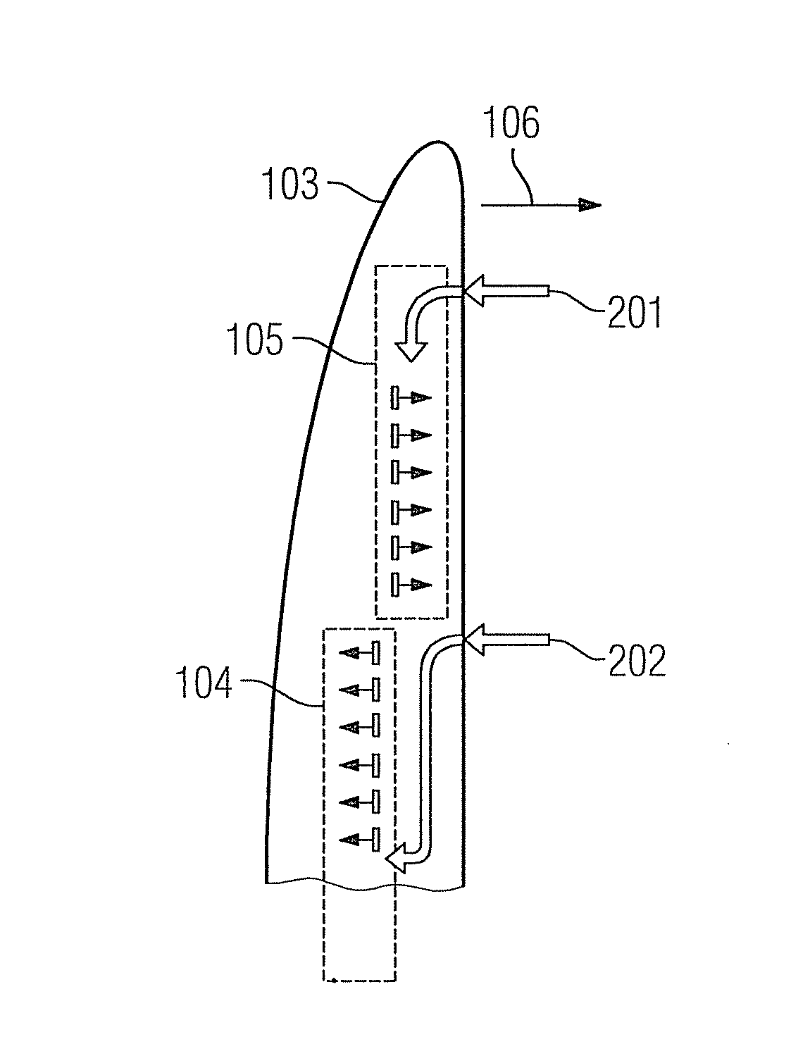
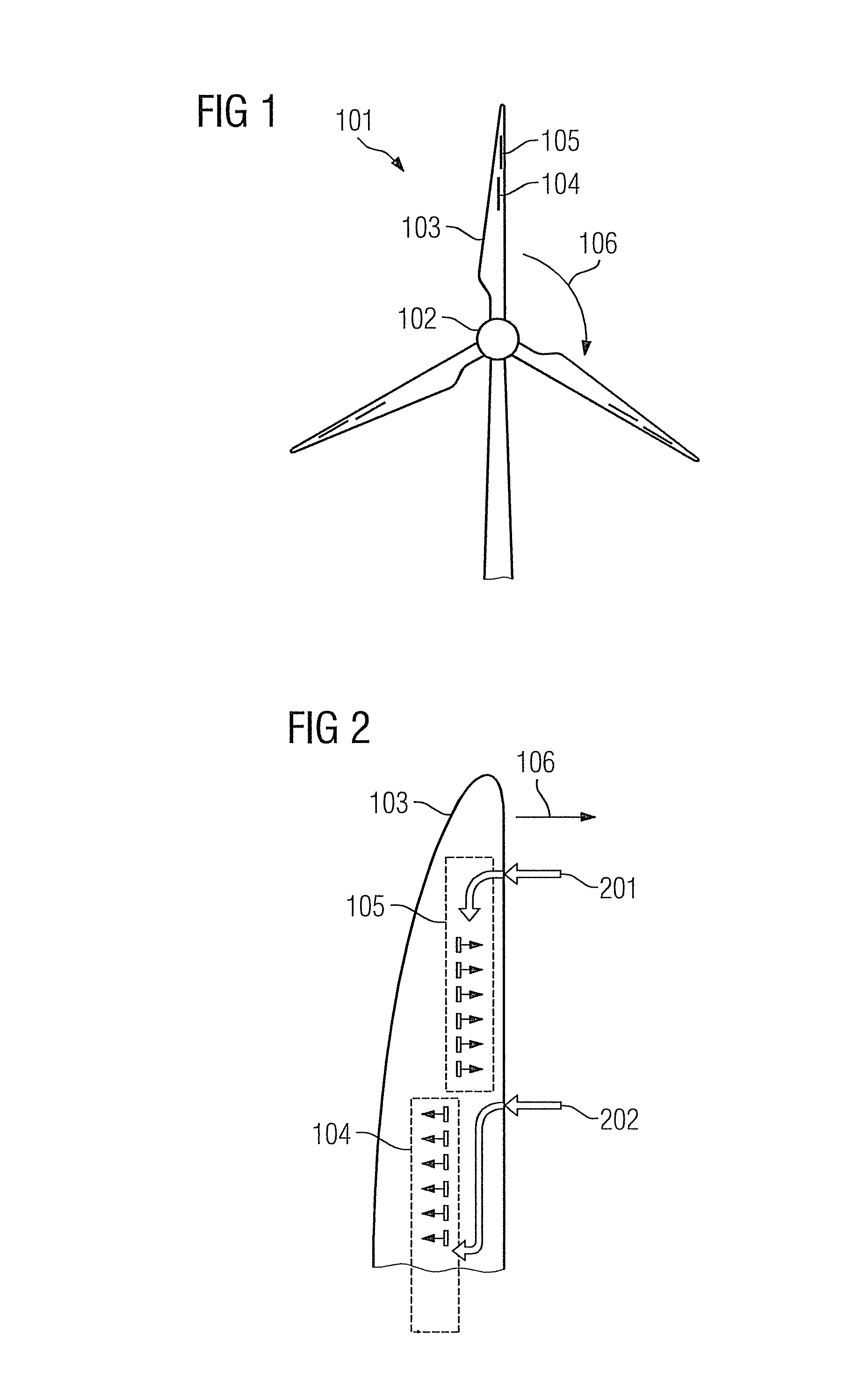
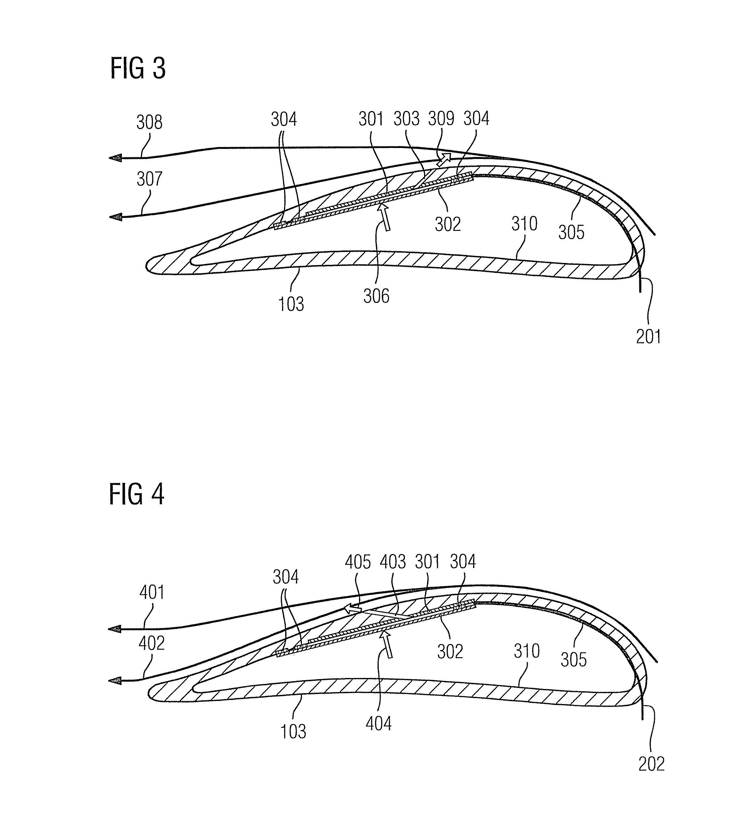
[0078]The present approach proposes providing an actuator to adjust the current on a rotor blade, wherein a strategy for setting the flow may be learned and in accordance with this strategy the actuation may be controlled.

[0079]The strategy considers in particular at least one of the following parameters:[0080]a stress on the rotor blade;[0081]a deflection of the rotor blade;[0082]a blade pitch;[0083]a rotor speed;[0084]a turbine alignment relative to the wind;[0085]a wind speed;[0086]shear winds;[0087]an air density;[0088]a temperature;[0089]turbulences or conditions which may result in turbulences.

[0090]The preceding parameters may be measured directly or derived from measured variables. It is also possible for at least one parameter to be learned and / or modeled e.g. based on (at least one) other available parameters or measured variables.

[0091]On the basis of the cited parameters, an (if necessary non-linear) model may be used in order to introduce a pulsing or (essentially) cont...


PUM


Abstract

A wind turbine rotor blade is equipped with an air chamber and equipped via the air chamber to route a modulation beam out of the rotor blade such that the air current along the rotor blade is changed. Thereby the laminar current is changed into a turbulent current on the one hand and its detachment and on the other hand its recreation is achieved in order to produce the laminar current. The control may occur via electrostatic actuators via a learnable control strategy based on neural forecasts, which take the complexity of the non-linear system into account and allow for the plurality of influencing factors. The stress on the rotor blades may be reduced, resulting in longer service life and reduced maintenance costs, a higher level of efficiency or quieter operation.

Description

CROSS REFERENCE TO RELATED APPLICATIONS[0001]This application claims priority of German Patent Office application No. 10 2011 079432.8 DE filed Jul. 19, 2011. All of the applications are incorporated by reference herein in their entirety.FIELD OF INVENTION[0002]The disclosure relates to a method for controlling a wind turbine, a rotor blade, which enables a corresponding control and an apparatus for controlling at least one rotor blade. Furthermore, a wind turbine having at least one such rotor blade and / or at least one such control apparatus is also proposed.BACKGROUND OF INVENTION[0003]The service life of a rotor blade of a wind turbine is to a large extent dependent on the strength of the cyclical stresses acting on the rotor blade based e.g. on wind shears, turbulences and initial conditions. High stresses in the form of deflections of the rotor blades are herewith unwanted, particularly if states with a high stress alternate in real-time with states without stress or even with ...

Claims


Application Information

Patent Timeline
Patent Type & Authority Patents(United States)
IPC IPC(8): F03D1/06F03D7/02
CPCF03D7/022F03D1/0675F05B2240/30Y02E10/721Y02E10/723Y02E10/72
Inventor DIXON, KRISTIAN ROBERTDULL, SIEGMUNDEGEDAL, PERESBENSEN, THOMASSTERZING, VOLKMAR
Owner SIEMENS AG
Why Eureka
Try Eureka