Light emitting device and light sheet
a light-emitting device and light-emitting sheet technology, which is applied in semiconductor devices, lighting and heating apparatuses, instruments, etc., can solve the problems of low light extraction efficiency of organic el devices, inability to achieve 100% extraction efficiency, and inability to efficiently extract light in every direction. achieve the effect of reducing luminance unevenness and color unevenness, improving light extraction efficiency, and reducing the effect of unevenness
- Summary
- Abstract
- Description
- Claims
- Application Information
AI Technical Summary
Benefits of technology
Problems solved by technology
Method used
Image
Examples
first embodiment
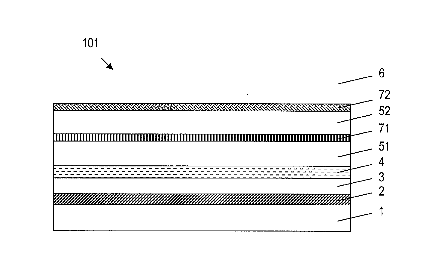
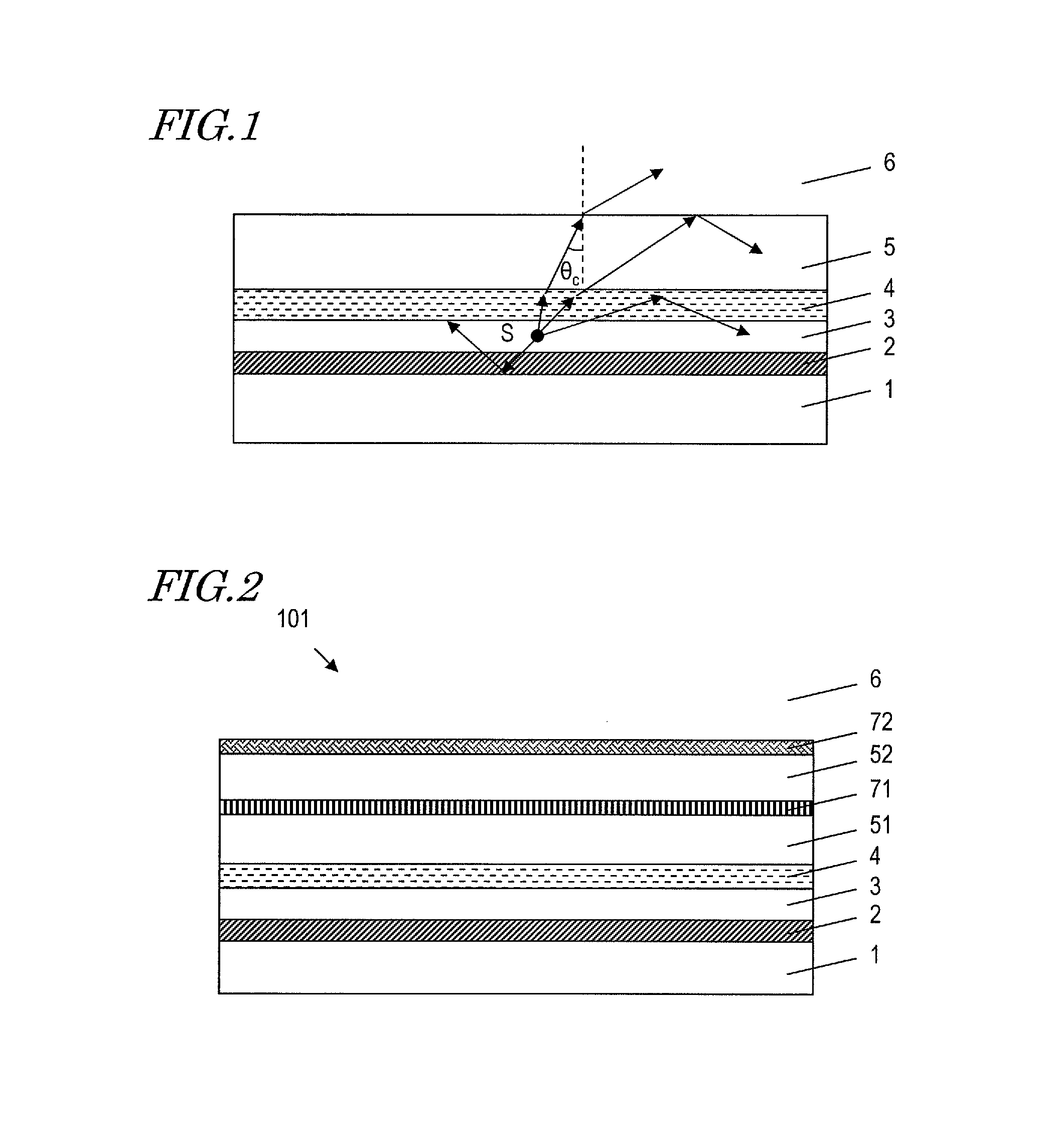
[0041]FIG. 2 schematically shows a cross-sectional structure of a first embodiment of the light-emitting device according to the present invention. The light-emitting device 101 includes an electrode 2 provided on a substrate an emission layer 3 located on the electrode 2, an electrode 4 located on the emission layer 3, a layer 51 located on the electrode 4, a diffraction grating structure 71 located on the layer 51, a layer 52 located on the diffraction grating structure 71, and a diffusion layer 72 located on the layer 52.
[0042]The present embodiment is effective for suppressing color unevenness, and therefore provides a particularly outstanding effect when using an emission layer 3 that emits white light. An example of a light-emitting device in which such an emission layer 3 is used may be a light-emitting device that incorporates an organic EL device, for example. In the case of organic EL, the emission layer 3 may sometimes be composed of plural layers in order to obtain a hig...
second embodiment
[0079]FIG. 15 schematically shows a cross-sectional structure of a second embodiment of the light-emitting device according the present invention. The light-emitting device 103 differs from the first embodiment in that a layer 53 which is located on the diffusion layer 72 is further included, the layer 53 being an air layer 6. The layer 53 is a protection layer for protecting the diffusion layer 72 from the exterior, for example.
[0080]When the diffusion layer 72 has its light-diffusing structure inside the diffusion layer 72, it is effectively as though the layer 53 also existed.
[0081]Therefore, even when the layer 53 is further included, this is essentially regardable as a diffusion layer in which the diffusion layer 72 and the layer 53 are integrated. The light-emitting device of the present embodiment provides similar effects to those of the first embodiment, although light may possibly be absorbed in the layer 53, causing a loss on the order of a few %.
third embodiment
[0082]FIG. 16 schematically shows a cross-sectional structure of a third embodiment of the light-emitting device according to the present invention. The light-emitting device 104 differs from the first embodiment in that the diffraction grating structure 71 and the diffusion layer 72 are switched in position, and that the electrode 2 is reflective.
[0083]Since the diffraction grating structure 71 and the diffusion layer 72 are switched in position, the diffusion layer 72 is located between the diffraction grating structure and the emission layer 3 in the present embodiment. Moreover, the electrode 2 has a structure that reflects light going out from the emission layer 3.
[0084]Therefore, with the light-emitting device 104, light which is reflected by the diffraction grating structure 71 and the diffusion layer 72 toward the emission layer 3 side is again reflected toward the diffusion layer 72 by the electrode 2, and allowed to go out to the exterior. In this case, the light which is ...
PUM
 Abstract
Description
Claims
Application Information
 - R&D
- Intellectual Property
- Life Sciences
- Materials
- Tech Scout
- Unparalleled Data Quality
- Higher Quality Content
- 60% Fewer Hallucinations
Browse by: Latest US Patents, China's latest patents, Technical Efficacy Thesaurus, Application Domain, Technology Topic, Popular Technical Reports.
© 2025 PatSnap. All rights reserved.Legal|Privacy policy|Modern Slavery Act Transparency Statement|Sitemap|About US| Contact US: help@patsnap.com


