System for bearing fault detection

a technology for bearings and faults, applied in the direction of mechanical measurement arrangements, mechanical roughness/irregularity measurements, instruments, etc., can solve the problems of reducing the intensity of generated ultrasound, generating a higher level of ultrasonic energy, and detecting good or bad bearings. , to achieve the effect of even more precise diagnosis of fault conditions

Active Publication Date: 2015-12-01
U E SYST
View PDF21 Cites 9 Cited by
  • Summary
  • Abstract
  • Description
  • Claims
  • Application Information

AI Technical Summary

Benefits of technology

[0014]The present invention provides an improvement over the traditional methods of detecting bearing faults. In the past one way of detecting bearing faults involved vibration monitoring using accelerometers. When monitoring a bearing with an accelerometer the signal that is generated is fairly broad band and contains many spurious frequency components that are not related to the four common types of defects. The present invention provides a system of analyzing fault frequencies that simplifies detection of specific bearing faults.
[0017]In another embodiment of the present invention, the software control module can connect to a Bluetooth circuit. This circuit allows the conversion of audio signals into short range wireless signals that can be picked up by a head set worn by the operator. This eliminates the need for a cable connecting the headphones to the portable unit.
[0020]The storage of heterodyned ultrasound, images and spectrums can be on removable media cards such as an SD or other removable media type. This allows information to be easily uploaded to a central computer or downloaded to the portable hand-held ultrasonic detector.

Problems solved by technology

Applying a lubricant to the device reduces friction and consequently reduces the intensity of the generated ultrasound.
Additionally, faulty devices, such as bearings, generate a higher level of ultrasonic energy than do good bearings and thus, whether the bearings are good or bad can also be detected.
However, a major reason for bearing failure is improper lubrication, not just a failure to lubricate.
In particular, over lubrication can be a problem.
Since acoustic energy created by faulty bearings is detectable in both the audible and ultrasonic frequency ranges, wherein the ultrasonic range is generally defined to be in the range of 28 kHz to 40 kHz, in noisy environments the audible components are too difficult to detect with the unaided human ear.
However, the detector disclosed in Peacock does not process the detected signal to produce an audible response, nor does it provide for signal attenuation after the initial pre-amplification stage.

Method used


Image

  • System for bearing fault detection
  • System for bearing fault detection
  • System for bearing fault detection

Examples


Embodiment Construction

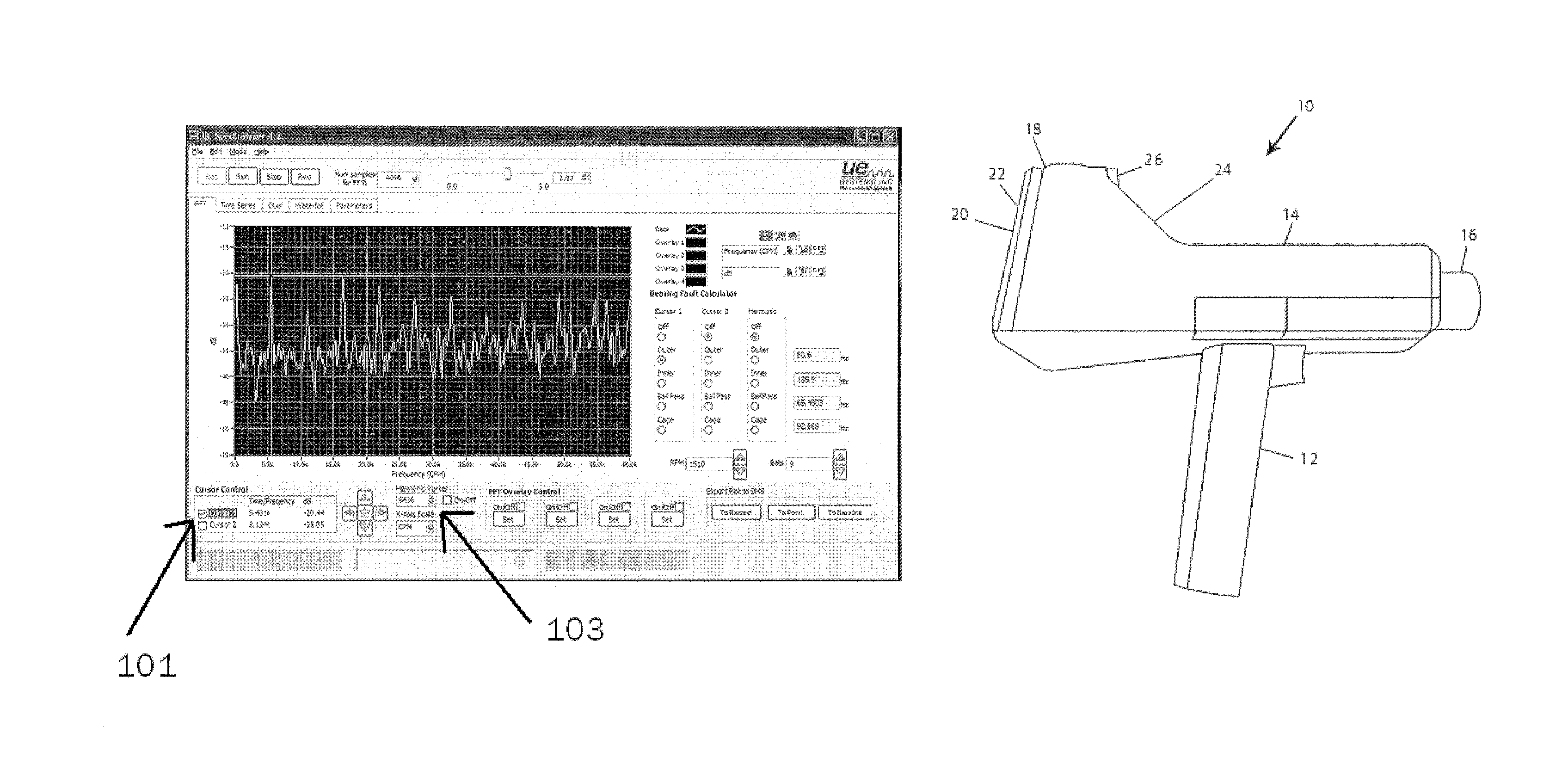
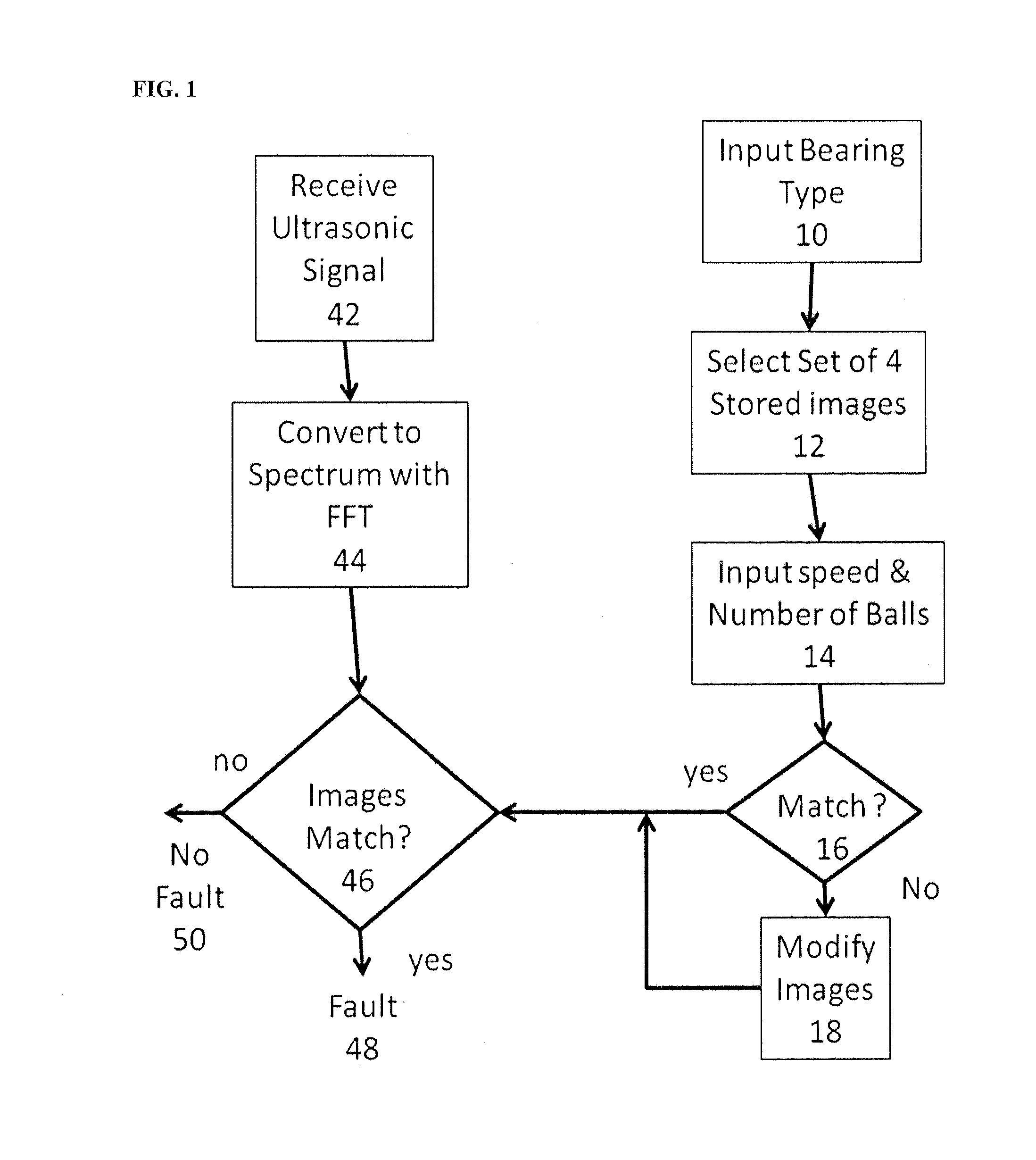
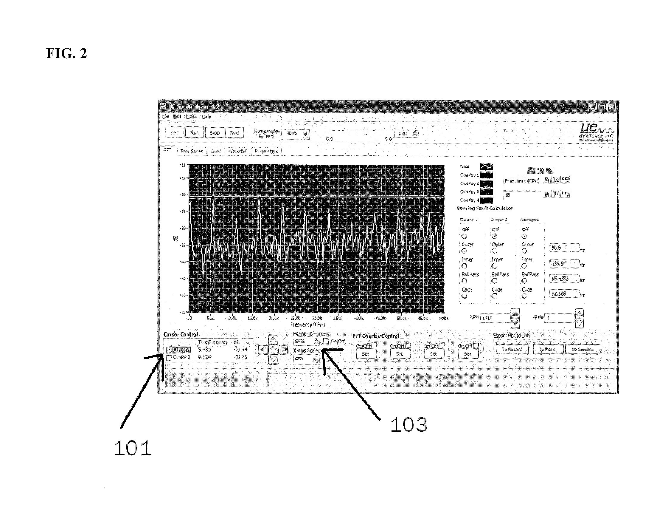
[0028]Referring now to the drawings wherein like references numerals designate corresponding parts throughout the several views. FIG. 1 is a flow chart of the operation of the software according to the present invention for automatically determining bearing faults. The process starts at step 10 when the operator inputs information on the type of bearing used in the motor under test. The input can be by means of a touch screen 20 located on the back of the hand-held ultrasonic detector unit as shown in FIG. 4. The input of the bearing type causes the software in step 12 to populate a database with data representing a typical; spectra response when that type of ball bearing has one of 4 specific fault types based on the fault frequency. For example, the database is constructed and populated using an algorithm to determine several common types of fault (1) an outer race defect, (2) an inner race defect, (3) a ball defect and (4) a bearing cage defect. The algorithm uses specific inputs...


PUM

PropertyMeasurementUnit
fault spectraaaaaaaaaaa
time series analysisaaaaaaaaaa
frequency spectrumaaaaaaaaaa

Abstract

The present invention is directed an ultrasonic frequencies fault detecting apparatus. The present invention uses high frequency ultrasonic energy signals to analyze bearings and determine the presence of faults therein. The ultrasonic return signals are heterodyned (by amplitude demodulation) into the audio spectrum for purposes of audio detection. In addition, a FFT spectrum of the signal is displayed on a monitor for more accurate results. According to the present invention software is used to automatically analyze the FFT spectrum by comparing the current spectrum with stored spectrums of known bearing conditions as modified based on the rotary speed of the bearing and the number of balls. Once a defect in a bearing has been located in this manner using automated FFT analysis, an operator can then use a device, such as a calibrated lubricant dispenser, to effectuate maintenance and / or repair.

Description

CROSS-REFERENCE TO RELATED APPLICATION[0001]This application claims the benefit of U.S. Provisional Patent Application Ser. No. 61 / 484,932, filed May 11, 2011 and entitled SYSTEM FOR BEARING FAULT DETECTION, the contents of which are herein incorporated by reference in its entirety. This application is also a continuation in-part of and claims the benefit of U.S. patent application Ser. No. 13 / 088,195 entitled ON-BOARD ULTRASONIC FREQUENCY SPECTRUM AND IMAGE GENERATION and U.S. patent application Ser. No. 13 / 088,212 entitled ULTRASONICALLY CONTROLLABLE GREASE DISPENSING TOOL, both filed Apr. 15, 2011, the contents of which are herein incorporated by reference in their entirety.BACKGROUND OF THE INVENTION[0002]1. Field of the Invention[0003]The invention relates generally to the use of Fast Fourier Transformations (FFT) for the visual identification of faults in roller bearing elements, by analysis of ultrasonic frequency emissions resulting therefrom.[0004]2. Description of the Rela...

Claims


Application Information

Patent Timeline
Patent Type & Authority Patents(United States)
IPC IPC(8): G01N29/00G01M13/02G01M13/04
CPCG01M13/045G01M13/028
Inventor GOODMAN, MARK A.BISHOP, WILLIAMMOHR, GARY
Owner U E SYST
Why Eureka
Try Eureka