Cooled smelt restrictor at cooled smelt spout for disrupting smelt flow from the boiler

a technology of restrictor and smelt, which is applied in the direction of water supply installation, process and machine control, instruments, etc., can solve the problems of abnormal or heavy smelt flow, large temperature difference between, and “banging” and explosions, etc., and achieve the effect of reducing the flow rate of smel

Active Publication Date: 2015-12-08
ANDRITZ INC
View PDF18 Cites 12 Cited by
  • Summary
  • Abstract
  • Description
  • Claims
  • Application Information

AI Technical Summary

Benefits of technology

[0011]A method, system and apparatus have been conceived for regulating the smelt flow at a smelt spout of a recovery boiler (e.g., in a cellulose pulp mill), utilizing at least a restrictor assembly comprising a restrictor plate. The smelt spout and a restrictor assembly may be cooled (e.g., by water or the like), so as to lower the temperature of the spout and restrictor assembly during periods of reduced or blocked smelt flow. The restrictor assembly and water-cooled smelt spout may advantageously control the flow rate and temperature of smelt discharged from a recovery boiler via the spout into a dissolving tank placed under the spout.
[0012]Thus, it may be desirable to improve the manner in which the flow of smelt is discharged from the smelt spout of a recovery boiler to the dissolving tank, and reduce the number of explosive reactions taking place in the dissolving tank. Accordingly, one skilled in the art may appreciate that there is a need for improved methods and apparatuses for controlling the flow rate and temperature of smelt flow from a recovery boiler into a dissolving tank via a smelt spout. This may advantageously help to reduce or control any reactions between the hot smelt flowing into the dissolving tank and the materials that are already in the dissolving tank. Certain example embodiments of the present invention seek to reduce explosions and other intense reactions between the hot smelt flowing into the dissolving tank and the lower-temperature materials already in the dissolving tank by implementing a restrictor apparatus / plate into or proximate to the smelt spout providing the pathway for smelt flow from the recovery boiler to the dissolving tank.
[0016]A method for restricting smelt flowing from a recovery boiler to a dissolving tank via a smelt spout, the method comprising: providing a restrictor assembly disposed proximate the smelt spout, between the recovery boiler and the dissolving tank, the restrictor assembly comprising at least a restrictor plate and an actuator for controlling the position of the restrictor plate; and controlling the position of the restrictor plate via the actuator such that the restrictor plate is in at least partial contact with the smelt so as to reduce a flow rate of the smelt from the recovery boiler to the dissolving tank.

Problems solved by technology

The hot smelt flow from the spout causes “banging” and explosions when the smelt falls into the cooler liquid in the dissolving tank.
The banging generally results from the large temperature differential between the smelt flow and the liquid in the dissolving tank.
However, the recovery boiler may be operated in an “upset” condition resulting in abnormal or heavy smelt flows.
These heavy smelt flows may not be adequately disrupted by the jets from the shatter jet nozzle and the smelt may cause explosions from which hot smelt droplets may splatter from the tank.
These excessive explosions of smelt can result in equipment damage and danger to personnel safety.

Method used


Image

  • Cooled smelt restrictor at cooled smelt spout for disrupting smelt flow from the boiler
  • Cooled smelt restrictor at cooled smelt spout for disrupting smelt flow from the boiler
  • Cooled smelt restrictor at cooled smelt spout for disrupting smelt flow from the boiler

Examples


Embodiment Construction

[0019]Referring now more particularly to the accompanying drawings in which like reference numerals indicate like parts throughout the several views.

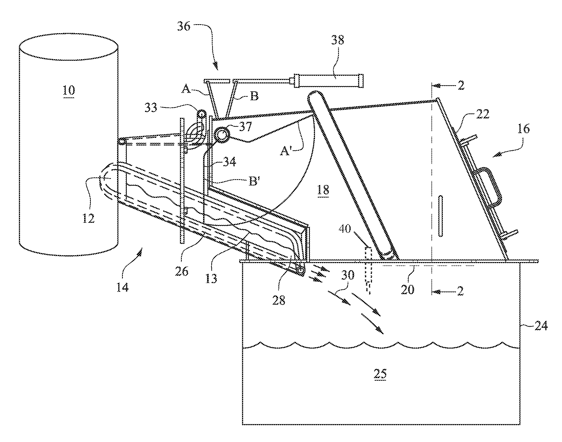
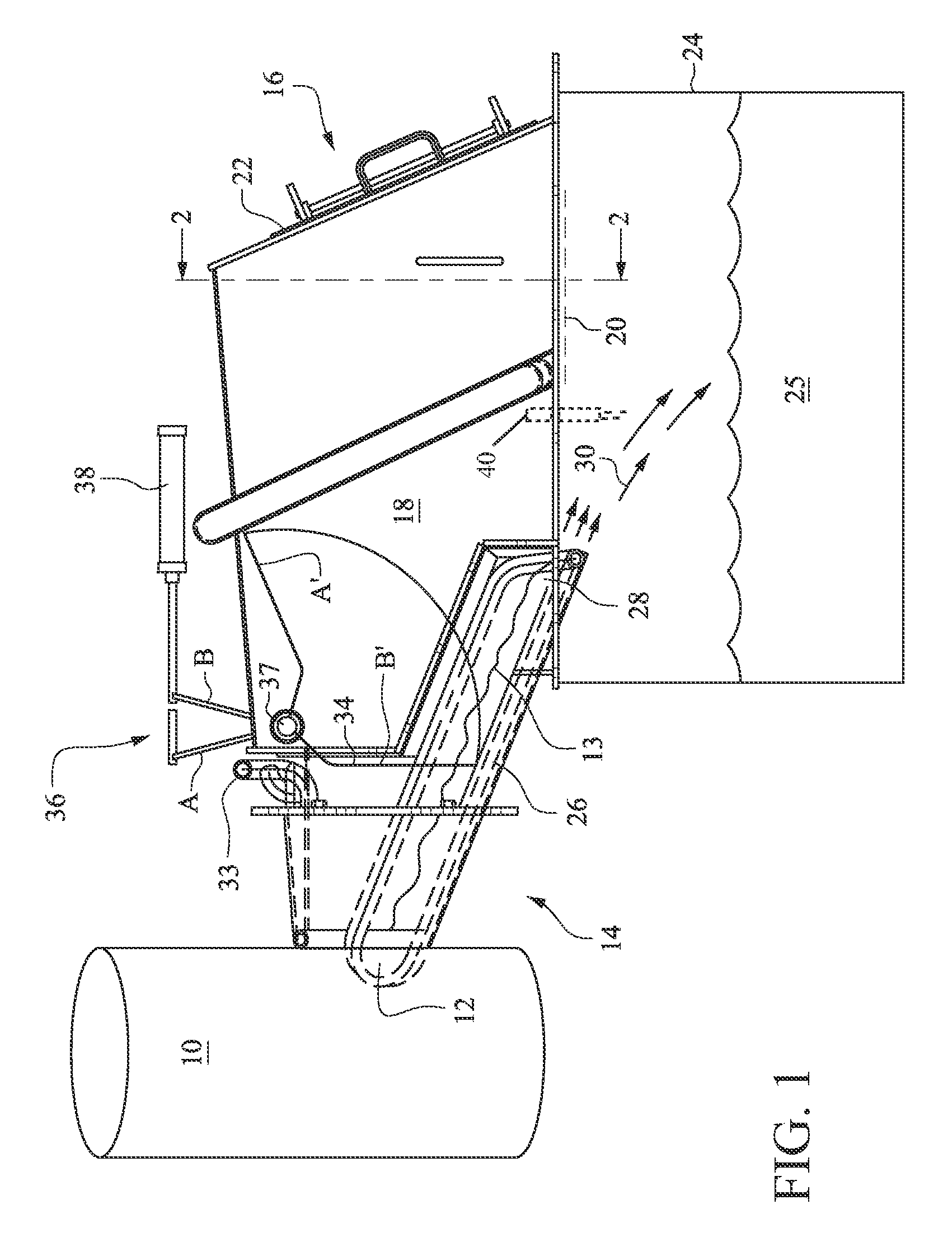
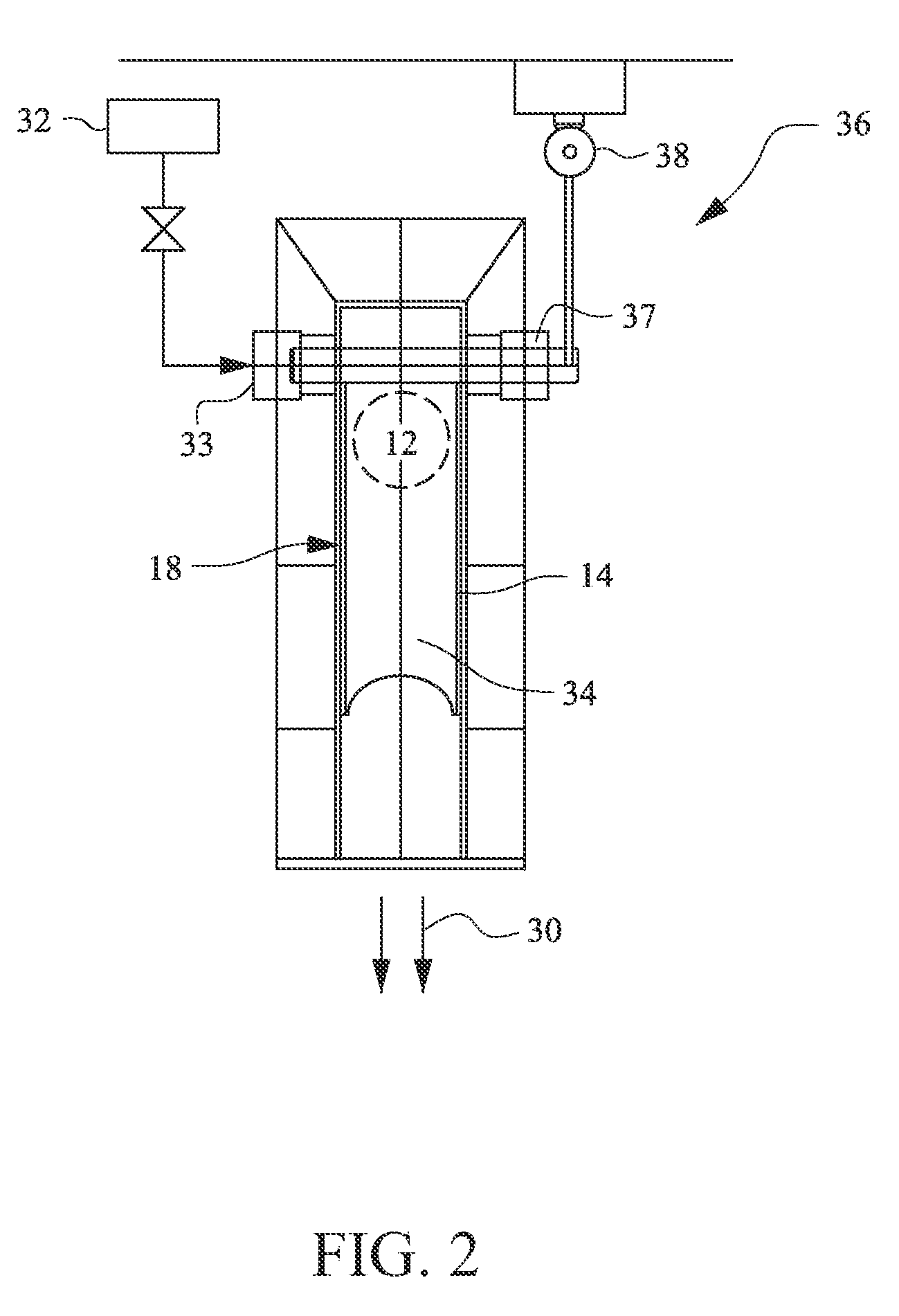
[0020]FIGS. 1 and 2 show a lower section of an example embodiment of a recovery boiler 10 of a pulp mill. Smelt flows from the bottom of the boiler 10 through an opening 12 and into a smelt spout 14. The portion of the smelt spout 14 extending outside the wall of the boiler is surrounded by a conventional closed protecting hood 16 comprising an upper hood portion 18 and a lower hood portion 20. The upper hood portion 18 includes a cover 22. The hood 16 contains the splash of liquid and smelt as they flow through the spout 14 and contains exhaust gases so that the gases do not discharge directly to the environment. The lower hood portion 20 may be connected to a conventional dissolving tank 24 disposed under the protecting hood 16. In the tank, the smelt is dissolved into liquid to produce, e.g., green liquor.

[0021]Hot, liquid smelt 13 f...


PUM

PropertyMeasurementUnit
rotationaaaaaaaaaa
temperatureaaaaaaaaaa

Abstract

The amount or extent of expositions as a result of hot smelt from a pulp mill recovery boiler impacting cool liquid in a dissolving tank is reduced more effectively by regulating the smelt flow via a restrictor assembly. The restrictor assembly may be positioned to permit the smelt to flow, unrestricted, from the recovery boiler to the dissolving tank, or the restrictor assembly may be positioned so as to fully or partially block the smelt flow from the boiler to the dissolving tank. In some embodiments, a source of cooling fluid may be coupled to the restrictor assembly so as to assist in cooling parts of the restrictor assembly when hot smelt is in contact with the assembly.

Description

[0001]This application claims priority to U.S. Provisional Patent Application No. 61 / 557,599, filed Nov. 9, 2011, the entire disclosure of which is hereby incorporated herein by reference.BACKGROUND[0002]The present invention relates to controlling smelt flow through and from a smelt spout of a recovery boiler to a dissolving tank.[0003]A recovery boiler, such as a soda recovery boiler, may be used in the chemical recovery of sulfate and other sodium-based substances from pulp manufacturing processes. In the recovery boiler, waste liquor, e.g., black liquor, from the pulping process is burned to transform cooking chemicals in the waste liquor into a form suitable for the recovery process.[0004]The waste liquor from a sulfate pulping process typically includes sodium, sulfur, organic substances and other compounds. The sodium and sulfur may be recovered using a recovery boiler. The organic substances dissolved in the waste liquor during the pulping process, e.g., digestion, are combu...

Claims


Application Information

Patent Timeline
Patent Type & Authority Patents(United States)
IPC IPC(8): F17D1/20F17D3/12D21C11/12
CPCD21C11/122Y10T137/0324
Inventor KUJANPAA, OLLI
Owner ANDRITZ INC
Why Eureka
Try Eureka