Fan blade system with multiple spaced layers of blades and centrifugal fan using same

a technology of centrifugal fan and blade system, which is applied in the direction of machines/engines, mechanical equipment, liquid fuel engines, etc., can solve the problems of reducing reliability in quality, affecting the efficiency of centrifugal fan operation, and the effect of forcing heat dissipation only limited by the air volume produced by one centrifugal fan, so as to reduce labor, time and material costs, and increase the airflow pressure and air volume. , the effect of increasing the air

Active Publication Date: 2015-12-08
ASIA VITAL COMPONENTS (CHINA) CO LTD
View PDF12 Cites 7 Cited by
  • Summary
  • Abstract
  • Description
  • Claims
  • Application Information

AI Technical Summary

Benefits of technology

[0010]A primary object of the present invention is to effectively solve the problems in the conventional dual centrifugal fan structure by providing a novel fan blade system with multiple spaced layers of blades, which enables a fan using same to have upgraded performance.
[0011]Another object of the present invention is to provide a fan blade system with multiple spaced layers of blades, which can be manufactured with reduced labor, time and material costs and requires only reduced power consumption.
[0012]A further object of the present invention is to provide a centrifugal fan that has upgraded overall performance.
[0013]A still object of the present invention is to provide a centrifugal fan that can be manufactured with reduced labor, time and material costs and requires only reduced power consumption.
[0014]To achieve the above and other objects, the fan blade system with multiple spaced layers of blades according to a preferred embodiment of the present invention includes a hub, a first blade group, and a second blade group. The hub has a top and a circumferential wall. The circumferential wall has a first end axially extended from a periphery of the top by a predetermined length to an opposite second end, and is axially divided into at least a first extension zone and at least a second extension zone located adjoining the first end and the second end of the circumferential wall, respectively. The first blade group includes a plurality of first blades outward extended from the first extension zone of the circumferential wall, and the second blade group includes a plurality of second blades outward extended from the second extension zone of the circumferential wall. And, the first blade group is axially spaced from the second blade group, and the first blades and the second blades are arranged in a staggered relation to one another. With this structural design, a centrifugal fan using the fan blade system of the present invention can have effectively upgraded overall performance and can be manufactured with reduced labor, time and material costs while requiring only reduced power consumption during operation thereof.
[0016]The fan blade system with multiple spaced layers is accommodated in the housing, and includes a hub, a first blade group, and a second blade group. The hub has a top and a circumferential wall. The circumferential wall has a first end axially extended from a periphery of the top by a predetermined length to an opposite second end and is axially divided into at least a first extension zone and at least a second extension zone located adjoining the first end and the second end of the circumferential wall, respectively. The first blade group includes a plurality of first blades outward extended from the first extension zone of the circumferential wall, and the second blade group includes a plurality of second blades outward extended from the second extension zone of the circumferential wall. And, the first blade group is axially spaced from the second blade group; the first blades and the second blades are arranged in a staggered relation to one another. When the fan blade system is mounted in the housing, the first and the second blade group are separately received in the secondary and the main receiving space, and are isolated from one another by the separating plate. With this structural design, a smoother flow field around the centrifugal fan can be formed to increase the airflow pressure and the air volume that can be produced by the centrifugal fan; and the centrifugal fan can be manufactured with reduced labor, time and material costs while requiring only reduced power consumption during operation thereof.

Problems solved by technology

However, electronic devices with these features tend to produce more and more heat during operation thereof and are therefore subjected to unstable operation and lowered reliability in quality.
However, the air volume produced by one single centrifugal fan has only limited effect in terms of forced heat dissipation effect.
While the conventional dual centrifugal fan structure 1 can produce increased total air volume, the actual amount of the air volume increased is limited.
Further, the conventional dual centrifugal fan structure 1 causes another problem.
Therefore, the flow field around the dual centrifugal fan structure 1 is unsmooth to adversely affect the overall performance of the dual centrifugal fan structure 1.
Moreover, in manufacturing and assembling the dual centrifugal fan structure 1, increased manufacturing and assembling costs are required because the smaller fan 12 is locked to the top of the larger fan 10 with a plurality of fastening elements 14 to consume extra labor and time.
As a result, the fan wheels of the larger and the smaller fan 10, 12 are not consistent in their rotating speeds and require two different power supplies to consume more power and further increase the use cost of the dual centrifugal fan structure 1.
In brief, the conventional dual centrifugal fan structure has the following disadvantages: (1) unsmooth flow field that prevents the fan structure from having improved total performance; (2) increased assembling labor and time costs and power consumption; and (3) increased manufacturing and use costs.

Method used


Image

  • Fan blade system with multiple spaced layers of blades and centrifugal fan using same
  • Fan blade system with multiple spaced layers of blades and centrifugal fan using same
  • Fan blade system with multiple spaced layers of blades and centrifugal fan using same

Examples


Embodiment Construction

[0028]The present invention will now be described with some preferred embodiments thereof and with reference to the accompanying drawings.

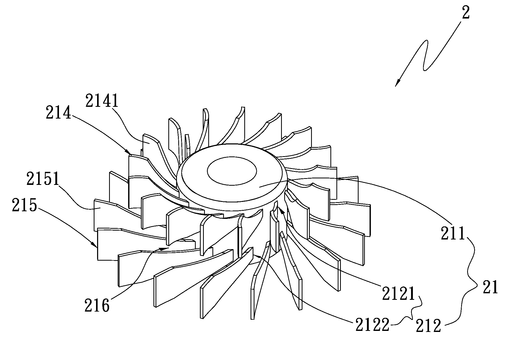
[0029]Please refer to FIG. 2 that is a perspective view of a fan blade system with multiple spaced layers of blades according to a first preferred embodiment of the present invention. For the purpose of conciseness, the first preferred embodiment of the present invention is also briefly referred to as “the fan blade system” and generally denoted by reference numeral 2 herein. As shown, the fan blade system 2 includes a hub 21, a first blade group 214, and a second blade group 215. The hub 21 includes a top 211 and a circumferential wall 212 having a first end axially extended from a periphery of the top 211 by a predetermined length to an opposite second end of the circumferential wall 212. The circumferential wall 212 is axially divided into at least a first extension zone 2121 and at least a second extension zone 2122. In the illustrated first p...


PUM


Abstract

A fan blade system with multiple spaced layers of blades and a centrifugal fan using same are disclosed. The centrifugal fan includes a housing, in which the fan blade system is mounted. The fan blade system includes a hub, and a first and a second blade group outward extended from a circumferential wall of the hub to axially space from each other. The housing includes a main housing portion and a secondary housing portion integrally formed on one side of the main housing portion. When the fan blade system is mounted in the housing, the two blade groups are separately located in the main housing portion and the secondary housing portion to produce higher airflow pressure and more air volume. With these arrangements, the centrifugal fan can have upgraded performance and be manufactured with reduced labor, time and material costs.

Description

FIELD OF THE INVENTION[0001]The present invention relates to a fan blade system and a centrifugal fan using same; and more particularly to a fan blade system with multiple spaced layers of blades that enables a centrifugal fan using same to have upgraded performance and be manufactured with reduced labor, time and material costs.BACKGROUND OF THE INVENTION[0002]Most of the currently available electronic devices, such as the notebook computers, are quickly developed to have high performance, high frequency, high operating speed and highly slim configuration. However, electronic devices with these features tend to produce more and more heat during operation thereof and are therefore subjected to unstable operation and lowered reliability in quality. To overcome the high amount of heat produced during the operation thereof, the electronic devices usually include a centrifugal fan as a heat dissipation device to achieve forced heat dissipation effect. However, the air volume produced by...

Claims


Application Information

Patent Timeline
Patent Type & Authority Patents(United States)
IPC IPC(8): F01D1/24F04D25/06F04D25/16
CPCF04D25/064F04D25/166F04D17/16F04D29/281
Inventor YUAN, MEIHUA
Owner ASIA VITAL COMPONENTS (CHINA) CO LTD
Why Eureka
Try Eureka