Touch display module and assembly method thereof

a technology of touch display module and assembly method, which is applied in the manufacture of electrode systems, electric discharge tubes/lamps, instruments, etc., can solve the problems of poor alignment precision between low process yield rate, and easy occurrence of the cover plate and the touch panel. achieve the effect of improving the yield rate of assembling and facilitating alignment precision

Active Publication Date: 2015-12-15
CHUNGHWA PICTURE TUBES LTD
View PDF7 Cites 0 Cited by
  • Summary
  • Abstract
  • Description
  • Claims
  • Application Information

AI Technical Summary

Benefits of technology

[0009]An assembly method of a touch display module having a preferable alignment precision for increasing yield rate in assembling is provided.
[0020]In view of above, the assembly method of the invention may sequentially disposing the backlight module, the display panel, the touch panel and the cover plate using opening design of the detachable module and adhesive layers disposition. In comparison to the prior art, the invention does not required to have the alignment pattern manufactured on the display panel and the touch panel for positioning, such that possibility of the alignment precision problem from happening may be reduce to further increase yield rate in assembling the touch display module. Also, member such as the front bezel, the back cover and the anti-splinted film used in prior art may also be omitted to effectively reduce overall thickness of the touch display module. In short, the touch display module of the invention may have a slimmer and lighter design while having a more preferable yield rate in assembling.

Problems solved by technology

With such assembly method, problems such as poor alignment precision between the cover plate and the touch panel and lower process yield rate due to foreign particles and / or gas bubble generated between the cover plate and the touch panel may easily occur.
The alignment precision problem may easily occur in the steps of said assembling and bonding processes, thus it usually requires a rework process to improve deviation caused by poor alignment.
However, the rework process may easily create a comprehensive destruction to said members, such that the assembling costs may be increased since integrity of members can not be retained.
As a result, such conventional design does not meet the compact size requirement in the modern electronic products.

Method used


Image

  • Touch display module and assembly method thereof
  • Touch display module and assembly method thereof
  • Touch display module and assembly method thereof

Examples


Embodiment Construction

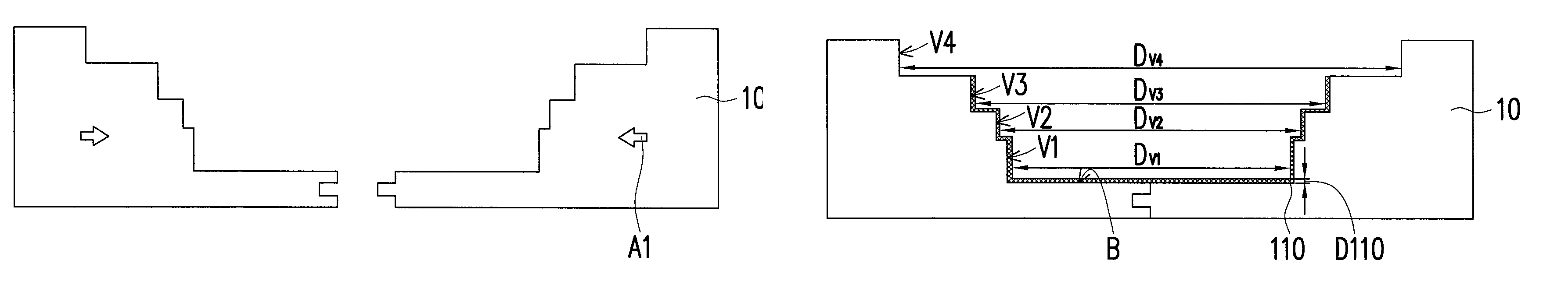
[0025]FIGS. 1A to 1M are schematic cross-sectional views illustrating a manufacturing method of a touch display module according to an embodiment of the invention. First, referring to FIG. 1A, a detachable mold 10 is provided. In the present embodiment, the detachable mold 10 may be, for example, a mold assembled with a symmetrically arranging method (e.g., to a direction shown by an arrow A1 in FIG. 1A), but the invention is not limited thereto. Hereinafter, the detachable mold 10 of the present embodiment is exemplified using metal as a material thereof. However, in other embodiments, the material of the detachable mold 10 may also be reinforced plastics or other appropriate materials.

[0026]Referring to FIG. 1B, the detachable mold 10 after assembly process includes a bottom portion B and a first opening V1, a second opening V2, a third opening V3 and a fourth opening V4 connected to pass each other and exposed outside of the bottom portion B. More specifically, the first opening ...


PUM

PropertyMeasurementUnit
thicknessaaaaaaaaaa
bore diameteraaaaaaaaaa
sizeaaaaaaaaaa

Abstract

A touch display module and an assembly method thereof are provided. The touch display module includes a backlight module, a cover plate, a display panel, a touch panel, a first adhesive layer, a second adhesive layer, a third adhesive layer and a fourth adhesive layer. The cover plate and the backlight module are disposed oppositely. The display panel is disposed between the backlight module and the cover plate. The touch panel is disposed between the display panel and the cover plate. The first adhesive layer covers around the backlight module, the display panel and the touch panel and a back portion of the backlight module. The second adhesive layer is disposed between the backlight module and the display panel. The third adhesive layer is disposed between the display panel and the touch panel. The fourth adhesive layer is disposed between the touch panel and the cover plate.

Description

CROSS-REFERENCE TO RELATED APPLICATION[0001]This application claims the priority benefit of Taiwan application serial no. 101137330, filed on Oct. 9, 2012. The entirety of the above-mentioned patent application is hereby incorporated by reference herein and made a part of this specification.BACKGROUND OF THE INVENTION[0002]1. Field of the Invention[0003]The invention relates to an electronic module and an assembly method thereof and more particularly, to a touch display module and an assembly method thereof.[0004]2. Description of Related Art[0005]Generally, the touch display module is composed by a touch module and a display module, in which the touch module includes a cover plate, a pressure sensitive adhesive, a touch panel and an anti-splinted film (ASF), and the display module includes a display module, a backlight module, a front bezel and a back cover. The back plate is configured to fix and mount the display panel and the backlight module, and the front bezel is circularly d...

Claims


Application Information

Patent Timeline
Patent Type & Authority Patents(United States)
IPC IPC(8): G06F3/041H01J9/24G02F1/13G02F1/1333
CPCG06F3/041H01J9/241G02F1/1303G02F1/13338G06F2203/04103G06F3/0412
Inventor HUANG, SHAO-KENGCHANG, SHENG-HUITUNG, YU-CHENGHSU, MING-TAN
Owner CHUNGHWA PICTURE TUBES LTD
Why Eureka
Try Eureka