Ion detection system and method

a detection system and detector technology, applied in the field of ion detection system and method, can solve the problems of reducing the life of the detector, affecting the detection accuracy of the detector, and the detector may not be sensitive enough to detect the least intense ion packet, so as to improve the detection accuracy, increase the lifetime, and reduce the cost and complexity

Active Publication Date: 2015-12-15
THERMO FISHER SCI BREMEN
View PDF67 Cites 27 Cited by
  • Summary
  • Abstract
  • Description
  • Claims
  • Application Information

AI Technical Summary

Benefits of technology

[0020]The present invention advantageously provides on-the-fly (i.e. dynamic) modulation of individual packets of secondary particles so that it is suitable for use as a TOF detector. The modulation can allow the detection system to keep both outputs below the limit of saturation and thus provide a significantly increased dynamic range. For example, the first output can be arranged such that it is always below a saturation level and modulation of the second output using the first output preferably ensures that the second output does not reach a saturation level or non-linear regime. Moreover, the detection system may be protected against the effects of intense ion packets, especially in embodiments wherein the modulation of the second output comprises attenuating the packet of secondary particles before the second output is produced. The invention thus may provide a detection system with an increased lifetime compared to prior art systems used in the same applications. The present invention may be implemented with a reduced cost and complexity compared to prior art detection systems for TOF, e.g. which utilise multiple channels and multiple gains.

Problems solved by technology

If the gain of the detector is reduced to avoid saturation by the most intense ion packets then the detector may not be sensitive enough to detect the least intense ion packets.
Thus, the dynamic range of the detector becomes compromised.
Moreover, the detector life may be reduced by the effect of intense ion packets.
This method, however, reduces sensitivity and does not protect the detector from intense ion packets.
This approach has the drawbacks that it requires an additional detector and more than one temporal focal point in the flight path, which is not feasible for some types of flight paths.
In addition to requiring two or more separate detectors, there is also no protection of the detector from intense ion packets in these arrangements.
Almost all of these techniques offer no protection of the detector from intense ion packets, an exception being the on-the-fly modulation of ion packets.
The detectors described therein would however not be suitable for detecting ions in a TOF mass spectrometer or faster scanning mass spectrometer where rise and fall times of the signals due to the incoming ion packets are typically of the order of a few nanoseconds (ns) long.

Method used


Image

  • Ion detection system and method
  • Ion detection system and method
  • Ion detection system and method

Examples


Embodiment Construction

[0045]In order to more fully understand the invention, various non-limiting examples of the invention will now be described with reference to the accompanying Figures in which:

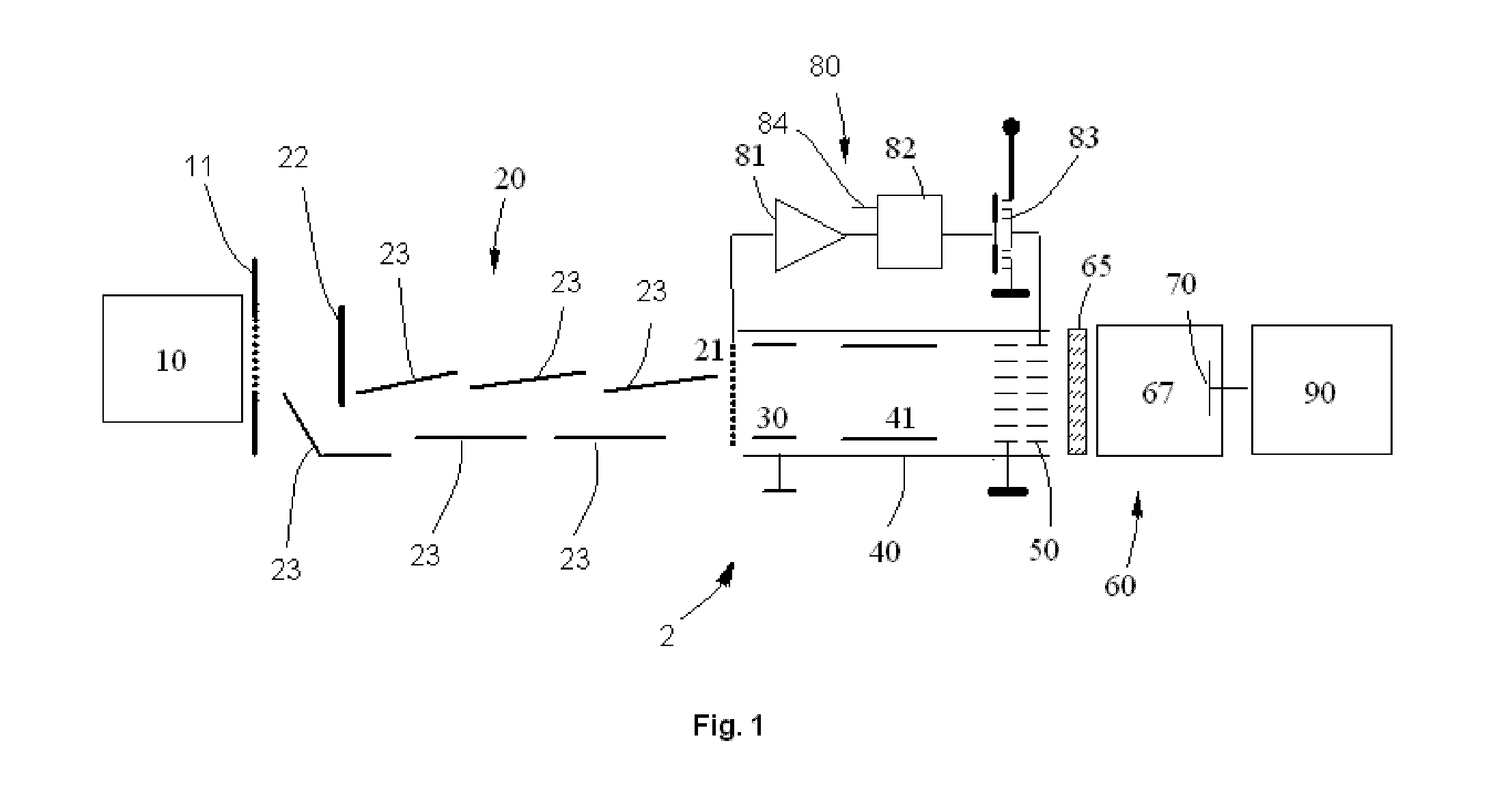
[0046]FIG. 1 shows schematically a first exemplary embodiment of a detection system and method according to the present invention;

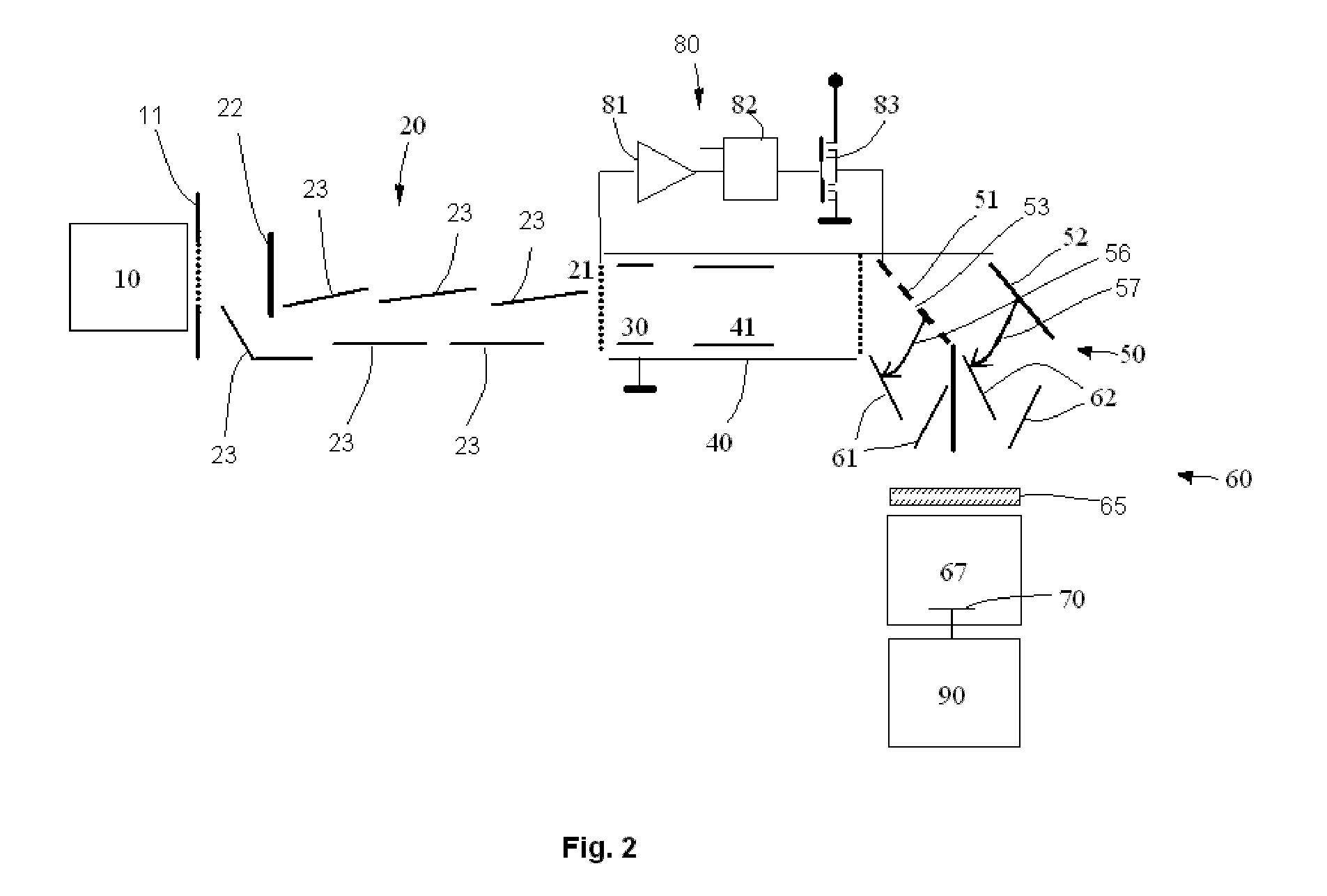
[0047]FIG. 2 shows schematically a second exemplary embodiment of a detection system and method according to the present invention comprising a low transmission gate;

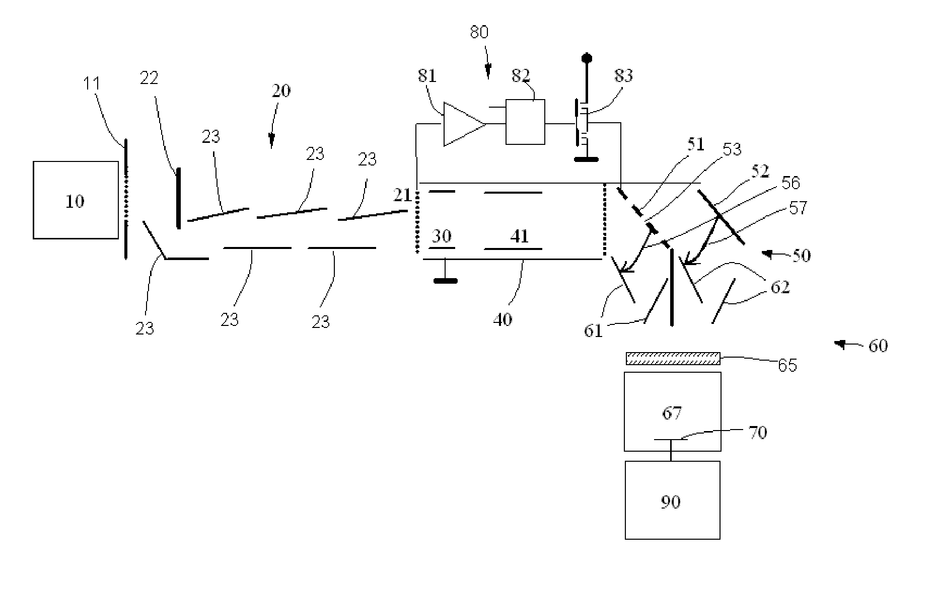
[0048]FIG. 3 shows schematically a third exemplary embodiment of a detection system and method according to the present invention comprising a high transmission gate; and

[0049]FIG. 4 shows schematically an exemplary embodiment of gating electronics for a detection system and method according to the present invention.

[0050]Referring to FIG. 1, there is shown an embodiment of the present invention which comprises a TOF mass analyser 10, which in use separates a short pulse of ions into a series of short ion packets accord...


PUM


Abstract

A detection system and a method for detecting ions which have been separated in a time-of-flight (TOF) mass analyzer, comprising an amplifying arrangement for converting ions into packets of secondary particles and amplifying the packets of secondary particles, wherein the amplifying arrangement is arranged so that each packet of secondary particles produces at least a first output and a second output separated in time and so that during the delay between producing the first and second output the first output produced by a packet of secondary particles is used for modulating the second output produced by the same packet. An increased dynamic range of detection and protection of the detection system against intense ion pulses is thereby provided.

Description

FIELD OF THE INVENTION[0001]This invention relates to an ion detection system and method for detecting ions. The system and method are useful for a time-of-flight mass spectrometer and thus the invention further relates to a mass spectrometer, particularly a time-of-flight mass spectrometer, comprising the ion detection system.BACKGROUND[0002]Time of flight (TOF) mass spectrometers are widely used to determine the mass to charge ratio (m / z) of ions on the basis of their flight time along a flight path. Ions are emitted from a pulsed ion source in the form of a short ion pulse and are directed along a prescribed flight path through an evacuated space to impinge upon or pass through an ion detector. The detector then provides an output to a data acquisition system. The ion source is arranged so that the ions leave the source with a constant kinetic energy and reach the detector after a time which depends upon their mass, more massive ions being slower. The ion pulse emitted from the s...

Claims


Application Information

Patent Timeline
Patent Type & Authority Patents(United States)
IPC IPC(8): H01J49/00H01J43/00H01J49/40H01J49/02
CPCH01J49/025H01J43/00H01J49/40H01J49/0031
Inventor KHOLOMEEV, ALEXANDERMAKAROV, ALEXANDER A.
Owner THERMO FISHER SCI BREMEN
Why Eureka
Try Eureka