

Capacitive blind-mate module interconnection
a capacitive coupling and blind-mate technology, applied in the field of blind-mate capacitive coupling interconnections, can solve the problems of time-consuming connection, degrading the electrical performance of an entire rf system, and requiring special skills
- Summary
- Abstract
- Description
- Claims
- Application Information
AI Technical Summary
Benefits of technology
Problems solved by technology
Method used
Image

Examples
Embodiment Construction
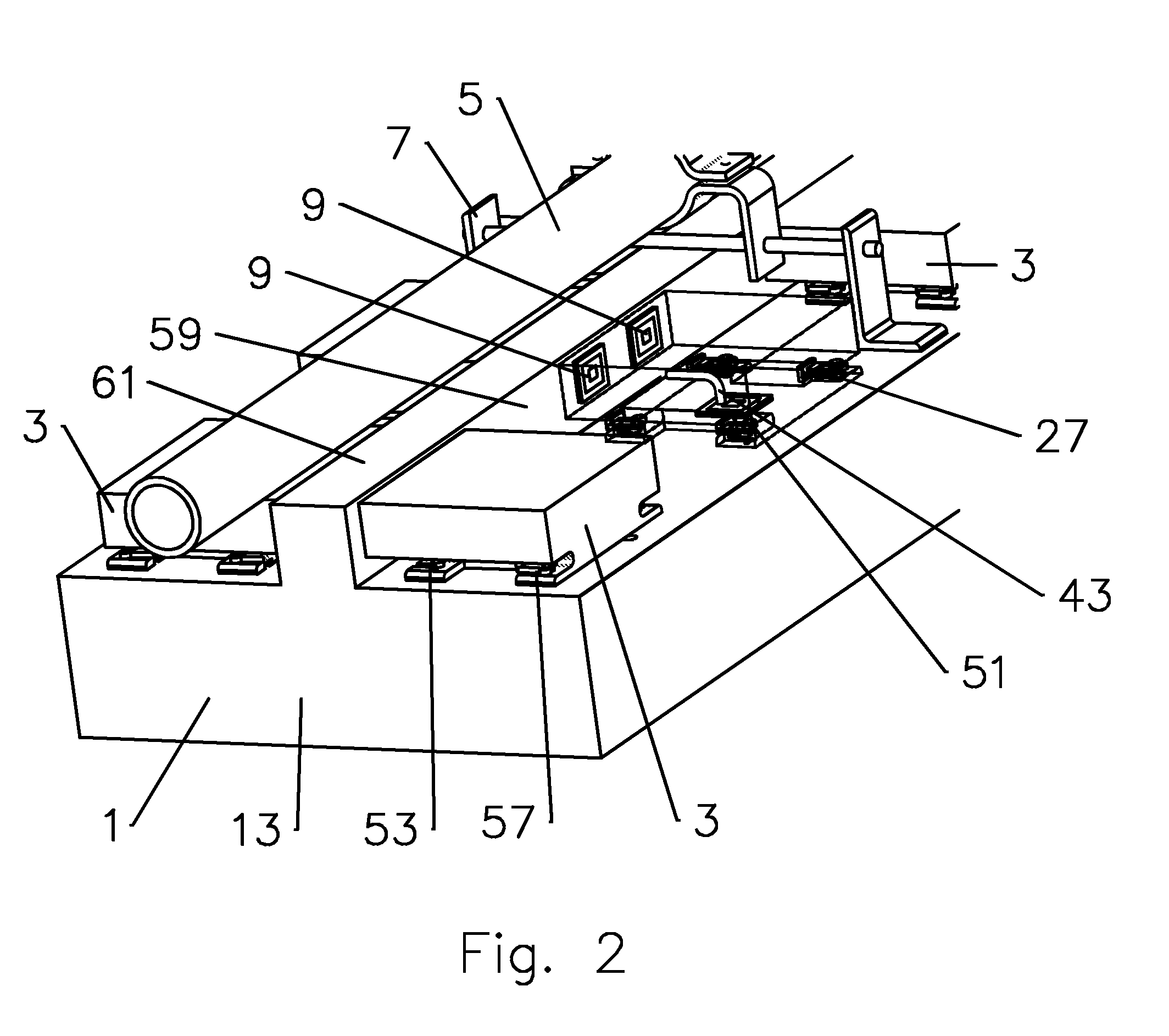
[0019]The inventor has recognized that PIM may be reduced and a blind-mate interconnection characteristic realized by providing generally planar capacitive coupling interconnection surfaces between a main module and one or more sub-modules coupled thereto.
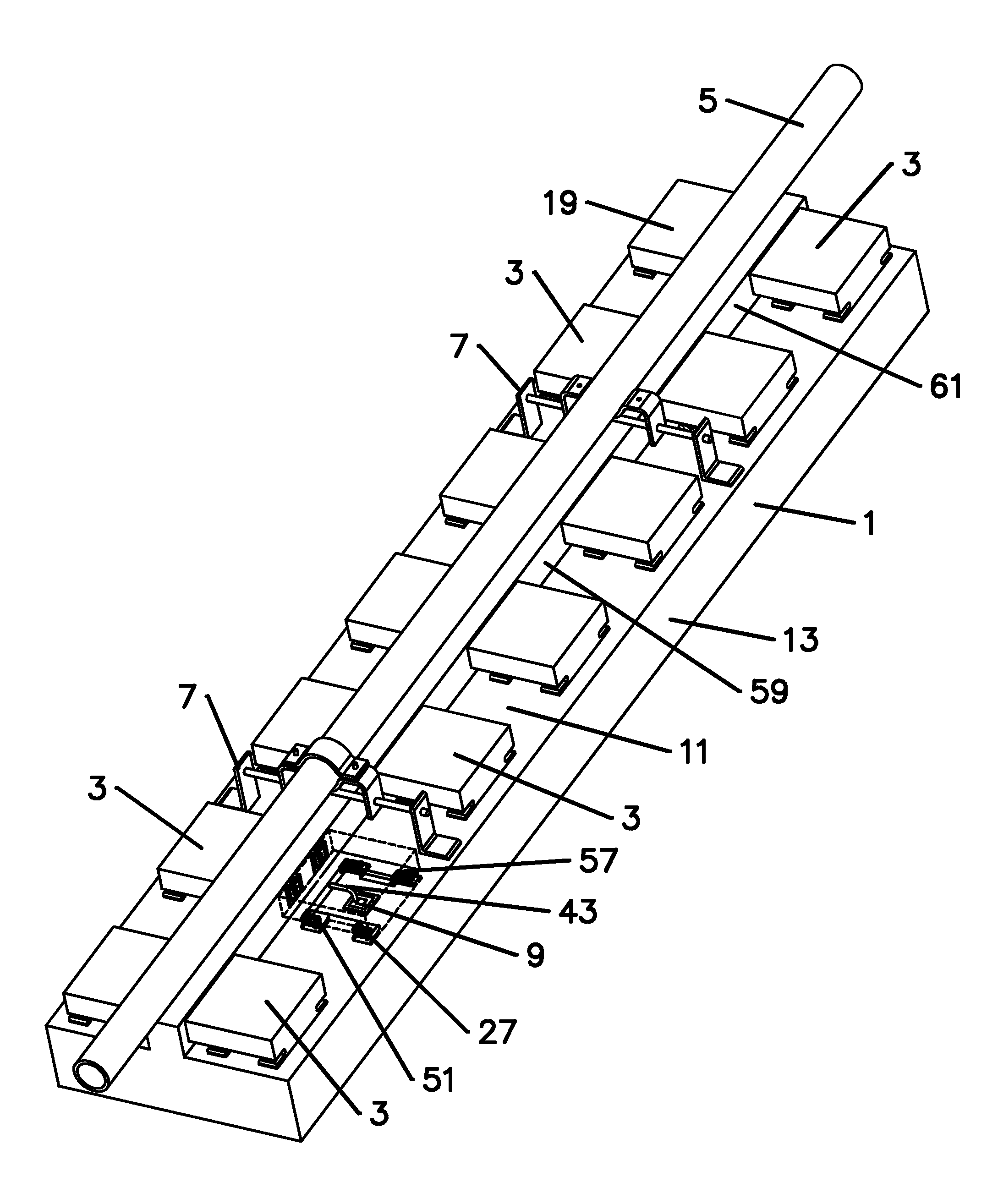
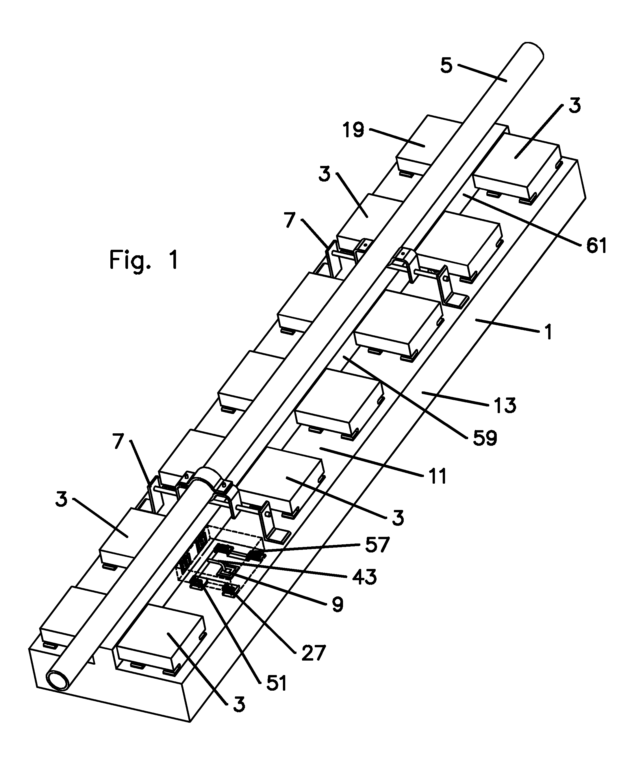
[0020]An exemplary capacitively coupled blind mate interconnection is demonstrated in FIGS. 1 and 2, wherein the main module 1 is an active antenna array with a plurality of field exchangeable interconnected sub-assemblies 3, such as transceiver modules. The main module 1 is demonstrated with typical mounting hardware, including a mounting pole 5 and mounting brackets 7. One skilled in the art will appreciate that it is advantageous for assembly, installation and / or maintenance operations to enable blind mating connection and disconnection between the main module 1 and each sub-module 3, without interfering with the adjacent sub-modules 3, main module brackets 7 and / or nearby structures, such as the mounting pole 5 or walls the mai...
PUM
 Abstract
Description
Claims
Application Information