Display device

a display panel and display technology, applied in the direction of electrical apparatus construction details, identification means, instruments, etc., can solve the problems of reducing the life affecting the normal operation affecting the brightness of the display panel, so as to achieve the effect of suppressing the drop in brightness

Active Publication Date: 2015-12-29
JOLED INC
View PDF19 Cites 8 Cited by
  • Summary
  • Abstract
  • Description
  • Claims
  • Application Information

AI Technical Summary

Benefits of technology

[0009]It is an object of the present invention to provide a display device which may suppress a drop in brightness caused by a local temperature rise in the center area of the display panel.
[0011]The display device according to the present invention may suppress a drop in brightness caused by a local temperature rise in the center area of the display panel.

Problems solved by technology

If there is a temperature rise inside the display panel, normal operations of the display panel are often interrupted.
A luminous layer of an organic EL element is likely to be susceptible to heat.
Therefore, a life of a display panel is shortened under an excessive temperature rise inside the display panel.
However, there is not appropriate transfer of heat generated by light emission to the radiator actually because of a low contact level between the display panel and the radiator.
Consequently, heat is accumulated inside the display panel to cause a temperature rise of the display panel.
Therefore, the luminous layer is likely to deteriorate.
Even if the radiation sheet of Patent Document 1 is used for heat dissipation of a display panel, there may be insufficient heat dissipation effect.
Consequently, the heat is confined to the center area of the display panel to cause a local temperature rise.
This results in a drop in brightness in the center area of the display panel.
Consequently, a drop in brightness in the center area of the display panel dramatically degrades quality of the video displayed by the display panel.

Method used


Image

  • Display device
  • Display device
  • Display device

Examples


first embodiment

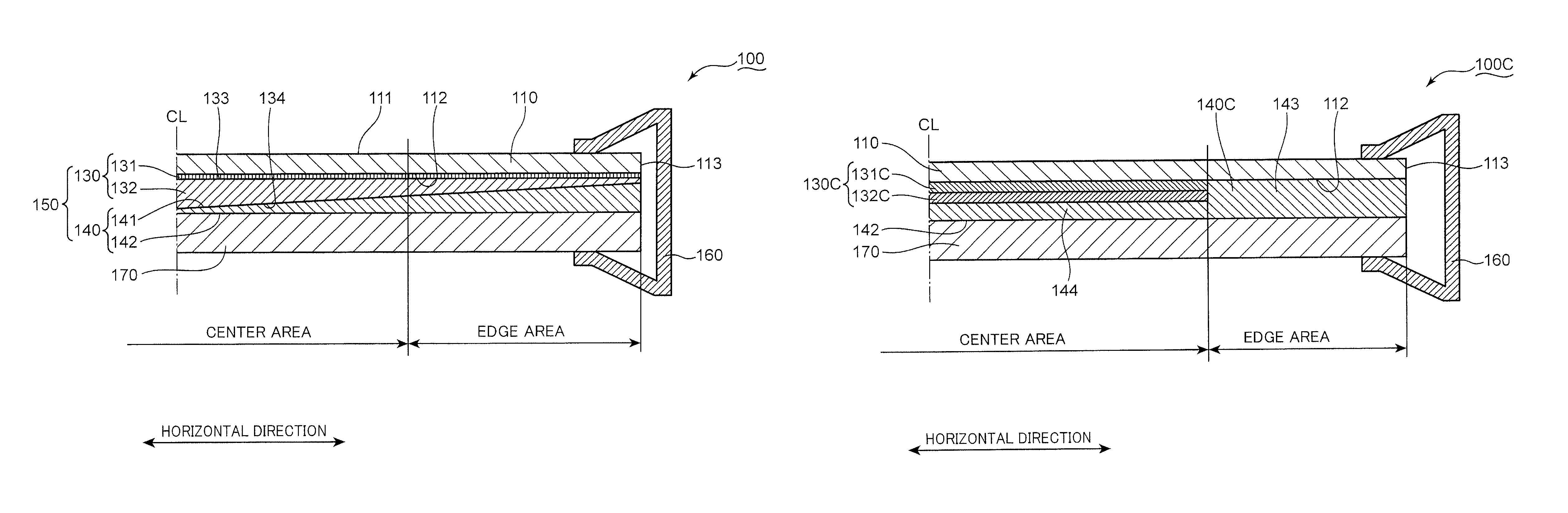
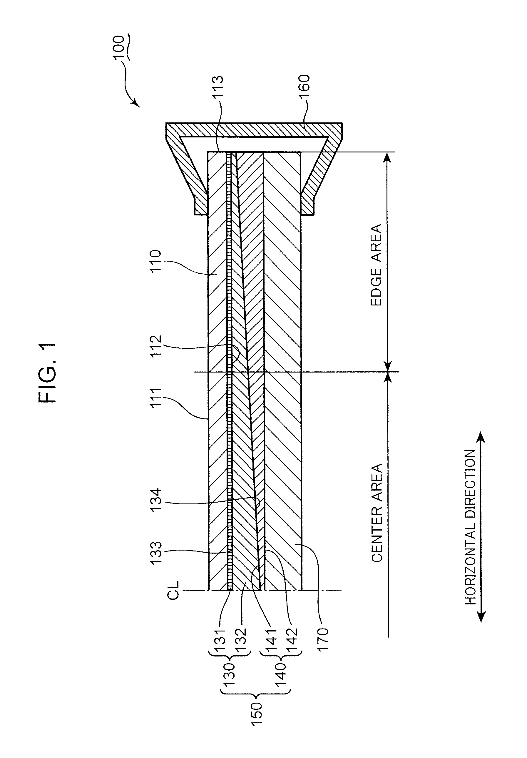
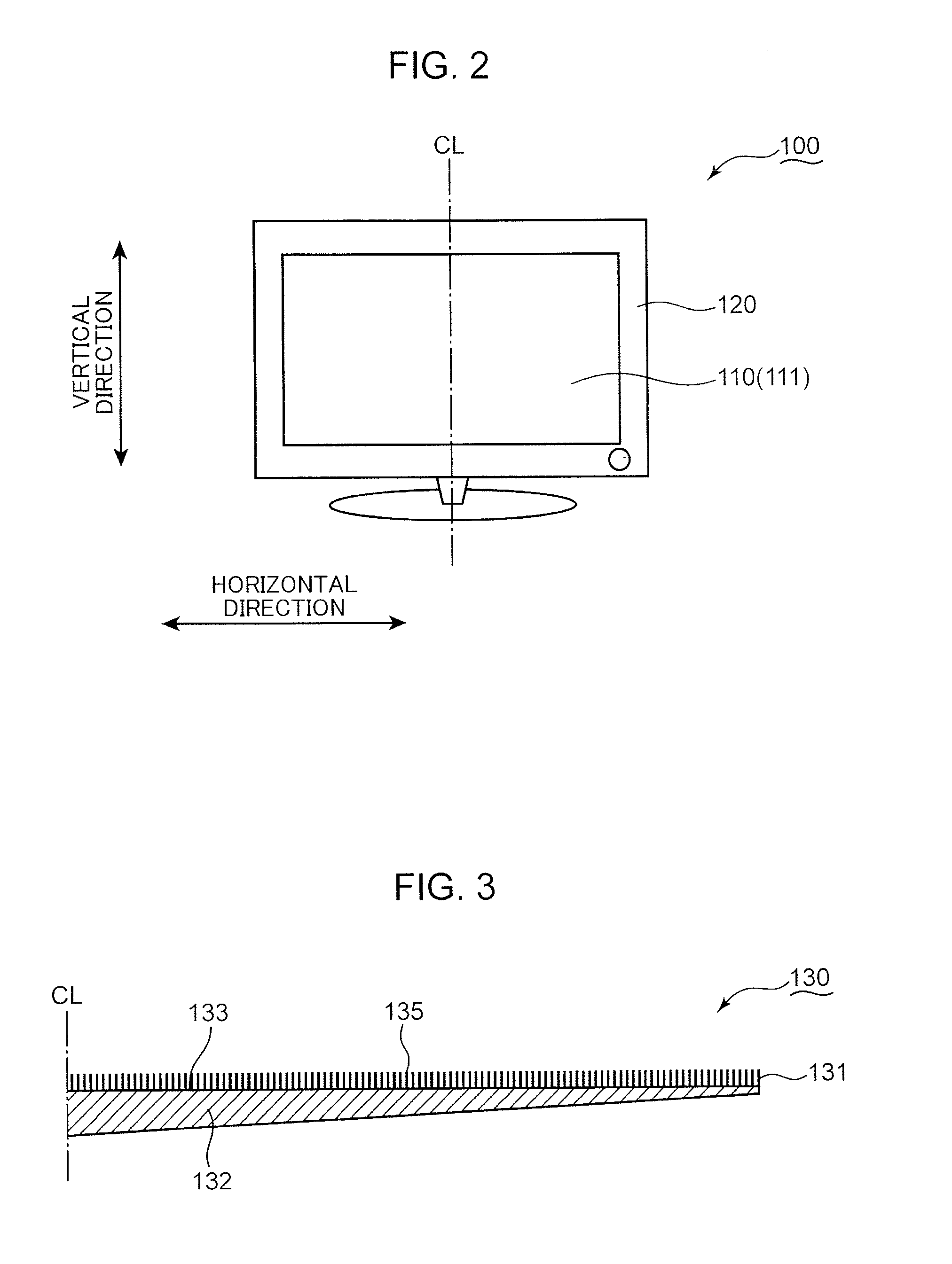
[0026]FIG. 1 is a schematic cross-sectional view of the display device 100 according to the first embodiment. FIG. 2 is a schematic front view of the display device 100 according to the first embodiment. The display device 100 is described with reference to FIGS. 1 and 2.

[0027]The display device 100 includes a display panel 110 configured to display images, and a housing 120 configured to support the display panel 110. The following various elements are stored in the housing 120.

[0028]In this embodiment, the display device 100 is used as a TV set. Alternatively, the display device 100 may be a display of a personal computer, a display of a portable telephone, a touch panel type information processor, or another device configured to display images.

[0029]In this embodiment, the display panel 110 is an organic EL display panel in which organic EL elements configured to emit light under current supply is incorporated. Alternatively, the display panel 110 may be a liquid crystal display ...

second embodiment

[0044]FIG. 4 is a schematic cross-sectional view of the display device 100A according to the second embodiment. The display device 100A is described with reference to FIG. 4. The same components as those of the display device 100 according to the first embodiment are denoted with the same reference symbols. Description about the same components as the first embodiment is omitted. Only differences from the display device 100 according to the first embodiment are described.

[0045]Like the display device 100 described in the context of the first embodiment, the display device 100A includes the display panel 110, the second thermal conduction layer 140, the heat sink 170 and the clamp 160. The display device 100A further includes a first thermal conduction layer 130A mounted on the mounting surface 112 of the display panel 110. The first thermal conduction layer 130A includes a flexible portion 131A, which is directly in contact with the mounting surface 112, and a thermal conduction pla...

third embodiment

[0048]FIG. 6 is a schematic cross-sectional view of the display device 100B according to the third embodiment. The display device 100B is described with reference to FIG. 6. The same components as those of the display device 100 according to the first embodiment are denoted with the same reference symbols. Description about the same components as the first embodiment is omitted. Only differences from the display device 100 according to the first embodiment are described.

[0049]Like the display device 100 described in the context of the first embodiment, the display device 100B includes the display panel 110, the second thermal conduction layer 140, the heat sink 170 and the clamp 160. The display device 100B further includes a first thermal conduction layer 130B mounted on the mounting surface 112 of the display panel 110. The first thermal conduction layer 130B includes a flexible portion 131B, which is directly in contact with the mounting surface 112, and a thermal conduction plat...


PUM


Abstract

The present application discloses a display device including a display panel for displaying images; a first thermal conduction layer including a flexible and compressively deformable portion in contact with the display panel, and a thermal conduction portion for conducting heat from the flexible portion; and a second thermal conduction layer in contact with the thermal conduction portion. The first thermal conduction layer conducts heat isotropically. The second thermal conduction layer with higher thermal conduction characteristics in an in-plane direction than the first thermal conduction layer forms a thermal conduction element with the thermal conduction portion. The thermal conduction element includes a first area corresponding to a center of the display panel and a second area closer to an edge of the display panel than the first area. The second area has higher thermal conductivity in the in-plane direction than the first area does.

Description

TECHNICAL FIELD[0001]The present invention relates to a display device configured to display images.BACKGROUND ART[0002]A display device in general includes a display panel configured to display images. The display panel typically includes luminous elements configured to emit light in response to image signals input to the display device. The luminous elements generate heat in synchronization with light emission to represent images. The heat from the luminous elements is likely to be confined inside the display panel. If there is a temperature rise inside the display panel, normal operations of the display panel are often interrupted.[0003]The display device may be exemplified by an organic EL (electroluminescence) display. The organic EL display includes organic EL elements. A luminous layer of an organic EL element is likely to be susceptible to heat. Therefore, a life of a display panel is shortened under an excessive temperature rise inside the display panel.[0004]In order to fa...

Claims


Application Information

Patent Timeline
Patent Type & Authority Patents(United States)
IPC IPC(8): H05K7/20G06F1/20G09F9/00H01L51/52
CPCH05K7/20963H01L51/529G09F9/00H10K59/8794H10K50/87
Inventor YAMAKITA, HIROYUKI
Owner JOLED INC
Why Eureka
Try Eureka