
Lighting apparatus using organic light emitting diode and manufacturing method thereof

a light emitting diode and light source technology, applied in the field of light source, can solve the problems of low color rendering index, low energy efficiency, and degraded luminous efficiency, and achieve the effects of suppressing the complexity of the manufacturing process, reducing the aperture ratio, and high electrical resistan

Active Publication Date: 2019-01-17
LG DISPLAY CO LTD
View PDF7 Cites 4 Cited by
  • Summary
  • Abstract
  • Description
  • Claims
  • Application Information

AI Technical Summary

Benefits of technology

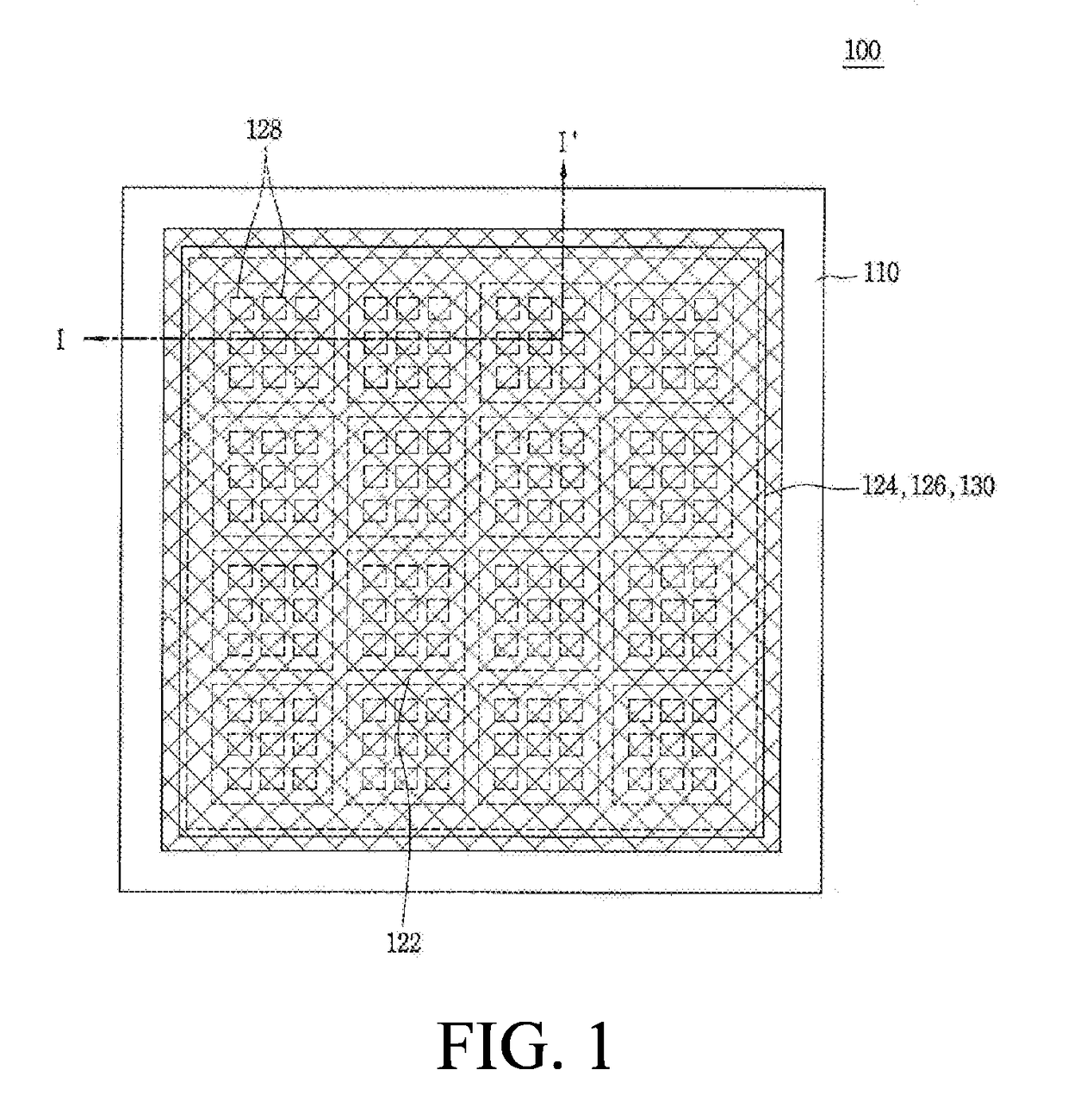
The present patent aims to provide a lighting apparatus where the short-circuit between the first and second electrodes of an organic light emitting diode is suppressed without adding complexity to the manufacturing process. Another aspect of the patent aims to improve the conductivity of the first electrode in each pixel by forming a transparent conductive pattern with low electrical resistance to prevent degradation of luminance due to the high electrical resistance of the first electrode.

Problems solved by technology

Among them, the incandescent lamps have a good color rendering index (CRI), but have a very low energy efficiency.
Further, the fluorescent lamps have a good efficiency, but have a low color rendering index and contain mercury, which may cause an environmental problem.
Therefore, there is a problem in that when a red light emitting diode, a green light emitting diode, and a blue light emitting diode are combined to emit white light, the luminous efficiency is degraded.
Further, there is an additional problem in that when the red light emitting diode, the green light emitting diode, and the blue light emitting diode are used, since widths of emission peaks are narrow, the color rendering property is also deteriorated.
However, in the case of the lighting apparatus which combines the blue light emitting diode and a yellow fluorescent material to output white light, since the fluorescent material which emits yellow light has a low luminous efficiency, there is a limitation in improvement of the luminous efficiency of the lighting apparatus.
However, in the organic light emitting diode used for the lighting apparatus, a distance between the anode and the cathode is small so that the anode and the cathode can be brought in direct contact with each other due to pinholes or cracks caused by permeation of foreign materials, a step of an internal structure of the organic light emitting diode, and roughness of laminated layers, so that a short-circuit can cause between the anode and the cathode.
Further, due to a process failure or a process error when the organic light emitting layer is formed, the organic light emitting layer is formed to be thinner than a desired thickness so that there may be a problem in that the anode and the cathode are electrically short-circuited.
When such an organic light emitting diode is applied to the lighting apparatus, light having luminance which is lower than a desired luminance is emitted due to the short-circuit of the anode and the cathode so that a quality of the lighting apparatus is degraded or even the lighting apparatus does not operate.
Further, when the organic light emitting diode is applied to the display device, pixels corresponding to the short-circuited area become defective pixels so that the quality of the display device is degraded.
Nonetheless, even in the clean room, the permeation of the foreign materials cannot be completely avoided and the short-circuit due to a structural problem such as a step of an internal structure of the organic light emitting diode and the roughness of the laminated layers cannot be avoided.
Therefore, the failure due to the short-circuit cannot be entirely avoided.

Method used


Image

  • Lighting apparatus using organic light emitting diode and manufacturing method thereof
  • Lighting apparatus using organic light emitting diode and manufacturing method thereof
  • Lighting apparatus using organic light emitting diode and manufacturing method thereof

Examples


Embodiment Construction

[0033]Reference will now be made in detail to the aspects of the present disclosure, examples of which are illustrated in the accompanying drawings. Whenever possible, the same reference numbers will be used throughout the drawings to refer to the same or like parts.

[0034]In the present disclosure, provided is a lighting apparatus including an organic light emitting diode formed of an organic material, rather than a lighting apparatus including an inorganic light emitting diode formed of an inorganic material.

[0035]The organic light emitting diode formed of an organic light emitting material has relatively excellent luminous efficiencies of red and green light as compared with an inorganic light emitting diode. Further, widths of emission peaks of blue, red, and green light of the organic light emitting diode are relatively broader than that of the inorganic light emitting diode so that a color rendering property is improved. Therefore, there is an advantage in that light of the lig...


PUM


Abstract

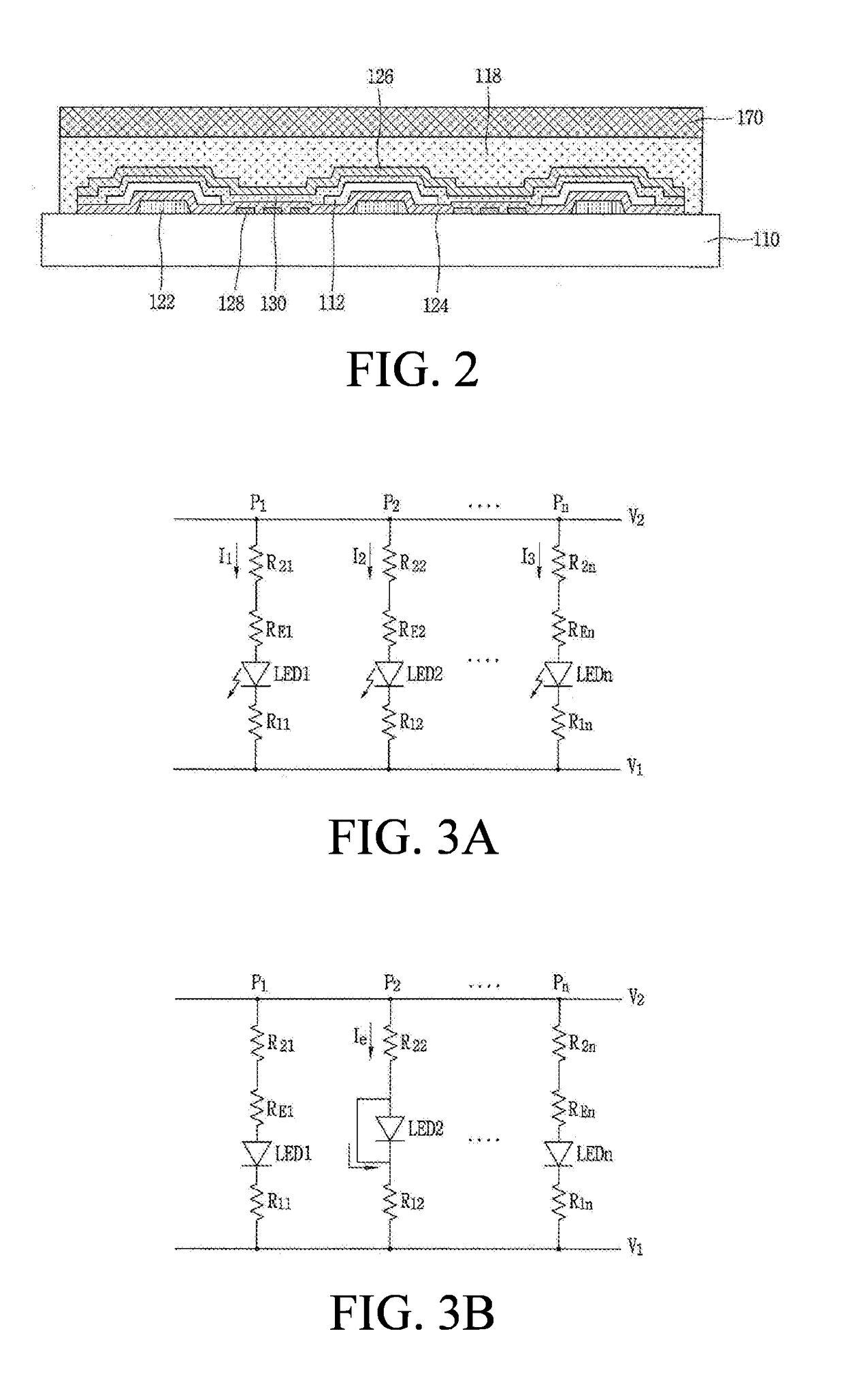
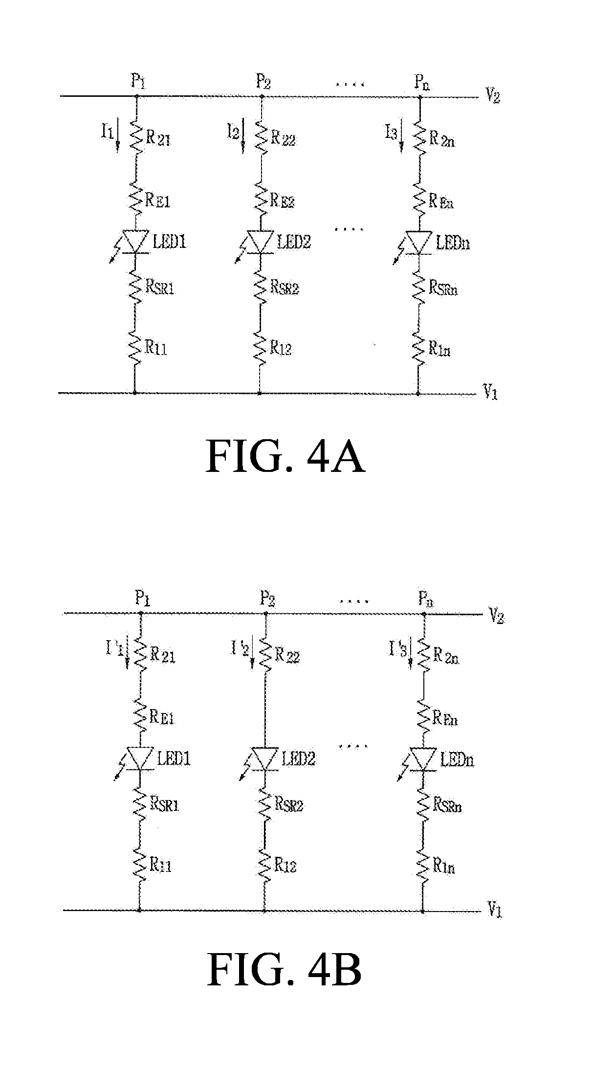
A lighting apparatus of the present disclosure includes an organic light emitting diode formed by a first electrode, an organic light emitting layer, and a second electrode on a first substrate and configures the first electrode by a transparent conductive material having an electrical resistance of 2800 to 5500Ω in each pixel. Therefore, even though the first electrode and the second electrode are in contact with each other to remove the electrical resistance by the organic light emitting layer in the pixel, the overcurrent is suppressed from being applied to the pixel by the electrical resistance of the first electrode. Further, at least one conductive pattern formed of a low electrical resistance transparent conductive material which is connected to the first electrode in the pixel is disposed to suppress the degradation of the luminance by the first electrode having a high electrical resistance.

Description

CROSS-REFERENCE TO RELATED APPLICATION[0001]This application claims the priority of Korean Patent Application No. 10-2017-0088075 filed on Jul. 11, 2017, in the Korean Intellectual Property Office, the disclosure of which is incorporated herein by reference in its entirety.BACKGROUNDField of the Disclosure[0002]The present disclosure relates to a lighting apparatus, and more particularly to, a light apparatus using an organic light emitting diode and a manufacturing method thereof. Although the present disclosure is suitable for a wide scope of applications, it is particularly suitable for preventing a failure due to a short-circuit between an anode and a cathode of the organic light emitting diode.Description of the Background[0003]Currently, fluorescent lamps or incandescent lamps are mainly used as lighting apparatuses. Among them, the incandescent lamps have a good color rendering index (CRI), but have a very low energy efficiency. Further, the fluorescent lamps have a good effi...

Claims


Application Information

Patent Timeline
Patent Type & Authority Applications(United States)
IPC IPC(8): H01L51/52H01L27/32H01L51/56H05B44/00
CPCH01L51/5212H01L27/3202H01L51/524H01L2251/5392H01L2251/558H01L2251/5361H01L51/56H10K59/80515H10K59/80516H10K59/80517H05B45/60Y02B20/30H10K2102/341H10K50/814H10K50/813H10K50/816H10K50/841H10K59/84H10K71/00H10K2102/351
Inventor SONG, TAEJOONKIM, JONGMIN
Owner LG DISPLAY CO LTD
Learn More