System and method for multipurpose traffic detection and characterization

a multi-purpose, traffic detection technology, applied in the field of system and method for traffic detection, can solve the problems of difficult to associate this information without, difficult to use automatic license plate recognition (alpr) system, and difficult to meet the high reliability requirements of this application

Active Publication Date: 2016-01-12
LEDDARTECH INC
View PDF343 Cites 24 Cited by
  • Summary
  • Abstract
  • Description
  • Claims
  • Application Information

AI Technical Summary

Problems solved by technology

In the case of speed infringement, determining the position and the lane, measuring accurately the speed of a specific vehicle in a multi-lane high-density highway, and associating this information without any ambiguity with the vehicle identified using an Automatic License Plate Recognition (ALPR) system is quite challenging.
There is a need for an automatic red light enforcement system but the high reliability required for this application is also challenging.
Intrusive detectors such as inductive loop detectors are still common for detecting the presence of vehicles but have some disadvantages such as lengthy disruption to the traffic flow during installation and maintenance, inflexibility and inability to track a vehicle.
Cameras with video processing have some drawbacks notably for speed measurement.
Radar technology is known to perform well for speed measurement but has some limitations in terms of lateral resolution making difficult the association between a speed measurement and the identification of a specific vehicle in dense traffic, for example, at an intersection.
Radar technology presents difficulties in the correlation of a specific speed measurement to a specific vehicle when two or more vehicles traveling at different speeds simultaneously enter into the measurement beam.
This limitation has an impact for speed enforcement applications.
Installation of radar technology for speed enforcement is demanding because it requires adjusting the angle of the axis of the main lobe of emission in both the horizontal and vertical directions with respect to the axis of the road, with accuracy typically less than one-half degree angle to limit the cosine effect.

Method used


Image

  • System and method for multipurpose traffic detection and characterization
  • System and method for multipurpose traffic detection and characterization
  • System and method for multipurpose traffic detection and characterization

Examples


Embodiment Construction

Description of the Multipurpose Traffic Detection System

[0083]Reference will now be made in detail to example embodiments. The system and method may however, be embodied in many different forms and should not be construed as limited to the example embodiments set forth in the following description.

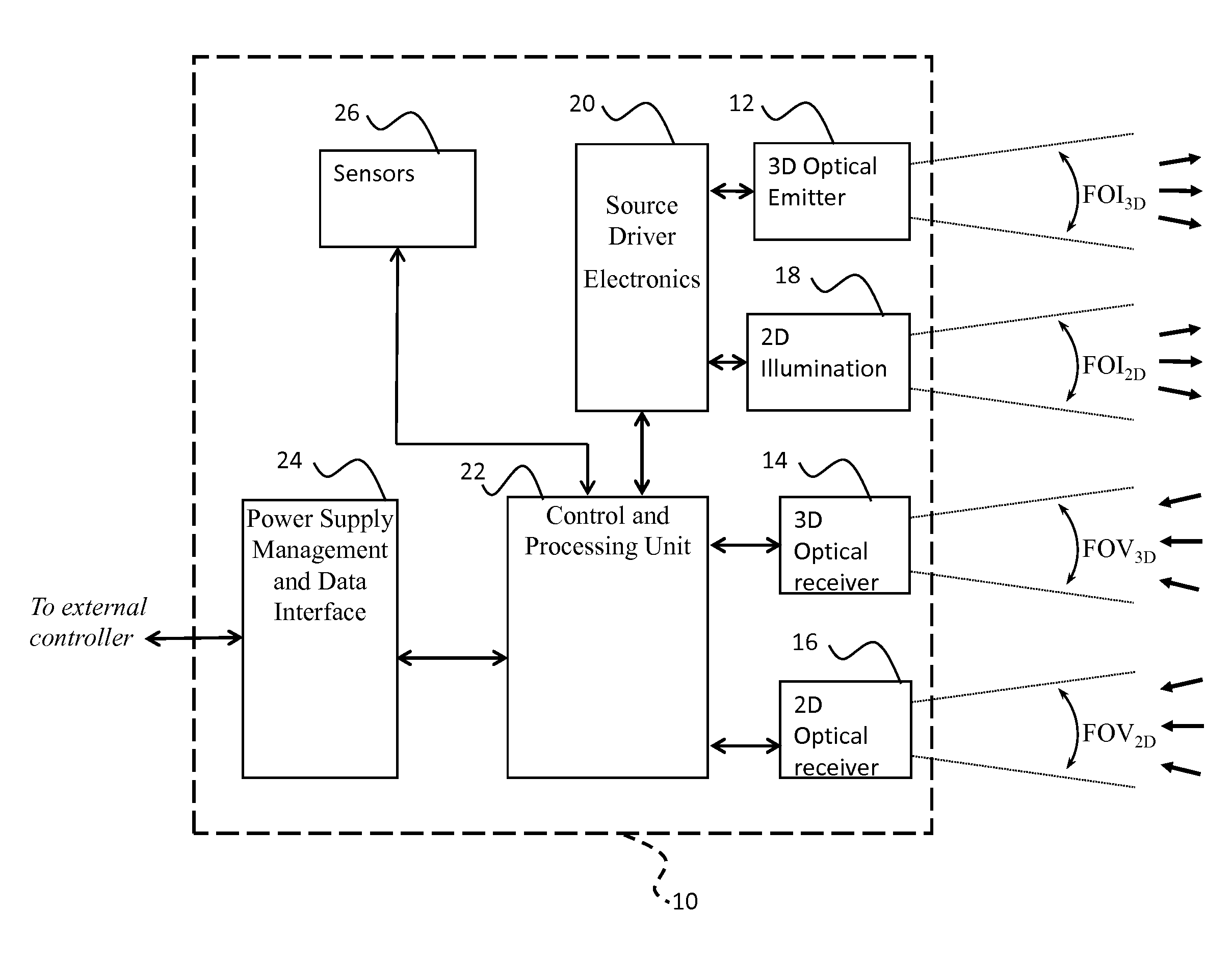
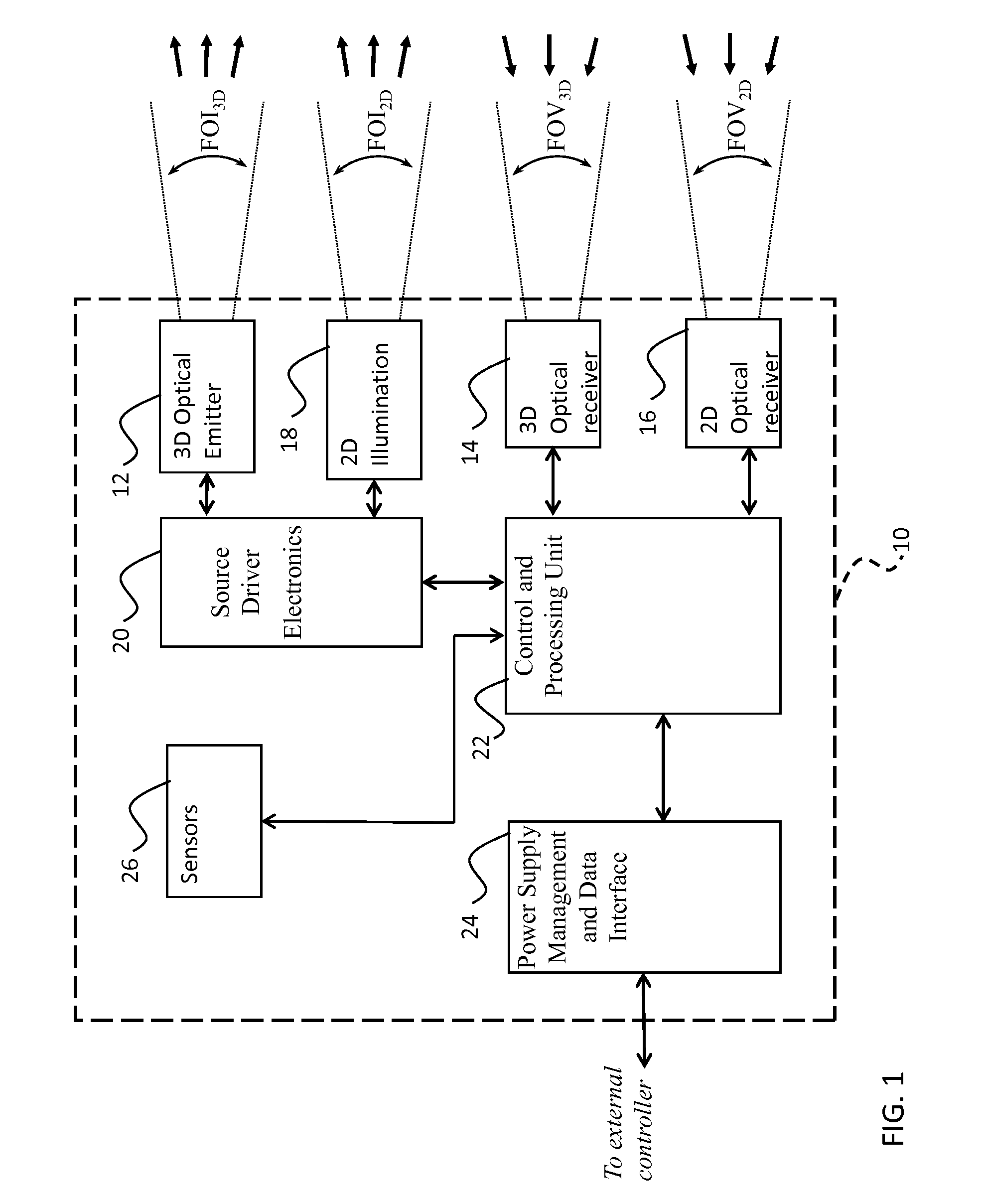
[0084]The functionalities of the various components integrated in an example multipurpose traffic detection system 10 can be better understood by referring to the functional block diagram shown in FIG. 1. The 3D Optical Emitter 12 (3DOE) emits short pulses of light, for example of a length less than 50 ns, within a predetermined zone. In the example embodiment, the 3DOE 12 is an IR LED illumination source determining a Field-of-Illumination FOI3D covering the 3D detection zone FOV3D. The optical source of the 3DOE can also be based on Laser technology. The horizontal angles of the FOI3D and FOV3D are wide enough to cover at least one lane. For example, a system with a horizontal FOI / FOV of...


PUM


Abstract

A method for tracking and characterizing a plurality of vehicles simultaneously in a traffic control environment, comprising: providing a 3D optical emitter; providing a 3D optical receiver with a wide and deep field of view; driving the 3D optical emitter into emitting short light pulses; receiving a reflection / backscatter of the emitted light, thereby acquiring an individual digital full-waveform LIDAR trace for each detection channel of the 3D optical receiver; using the individual digital full-waveform LIDAR trace and the emitted light waveform, detecting a presence of a plurality of vehicles, a position of at least part of each vehicle and a time at which the position is detected; assigning a unique identifier to each vehicle; repeating the steps of driving, receiving, acquiring and detecting, at a predetermined frequency; tracking and recording an updated position of each vehicle and an updated time at which the updated position is detected.

Description

TECHNICAL FIELD[0001]The present invention relates to a system and method for traffic detection and more particularly to an optical system that detects the presence, location, lane position, direction and speed of vehicles in a traffic zone using an active three-dimensional sensor based on the time-of-flight ranging principle and an image sensor.BACKGROUND OF THE ART[0002]Growth in transportation demand has a major impact on traffic congestion and safety. To enhance the on-road safety and efficiency, major investments in transport infrastructures, including capital, operation and maintenance, are made all over the world. Intelligent systems collecting and disseminating real time traffic information is a key element for the optimization of traffic management.[0003]Traffic monitoring can consist in different activities such as detecting the presence of a vehicle in a specific zone, counting the number of vehicles (volume), determining the lane position, classifying each vehicle, deter...

Claims


Application Information

Patent Timeline
Patent Type & Authority Patents(United States)
IPC IPC(8): G08G1/01G06T7/20G01S17/02G06K9/00G08G1/04G01S7/484G01S7/48G01S17/89G01S17/88G01S17/66G01S17/58G06K9/32G01S17/86G08G1/015G08G1/017G08G1/054G08G1/065
CPCG06K9/00785G06K9/3241G06T7/208G08G1/015G08G1/0175G08G1/04G08G1/054G01S17/023G08G1/0125G01S7/4802G01S17/58G01S17/66G01S17/88G01S17/89G01S7/484G01S7/4808G06K2209/23G06T2200/04G06T2207/10028G06T2207/30236G06T7/277G01S17/86G06V20/54G06V10/255G06V2201/08
Inventor MIMEAULT, YVANGIDEL, SAMUEL
Owner LEDDARTECH INC
Why Eureka
Try Eureka