Turbocharger compressor inlet flow control

a technology of turbocharger compressor and inlet flow control, which is applied in the direction of machines/engines, mechanical equipment, non-fuel substance addition to fuel, etc., can solve the problems of limiting the flow capacity of high-end compressors, adversely affecting the flow loss of high-end performance compressors, and affecting the flow of high-end performance turbines. , to achieve the effect of increasing the torque/power output density of the engine, increasing the pressure in the intake manifold,

Active Publication Date: 2016-01-26
FORD GLOBAL TECH LLC
View PDF30 Cites 9 Cited by
  • Summary
  • Abstract
  • Description
  • Claims
  • Application Information

AI Technical Summary

Benefits of technology

[0001]Engines may use a turbocharger to increase engine torque / power output density. In one example, a turbocharger may include a compressor and a turbine connected by a drive shaft, where the turbine is coupled to the exhaust manifold side and the compressor is coupled to the intake manifold side. In this way, the exhaust-driven turbine supplies energy to the compressor to increase the pressure in the intake manifold (e.g. boost, or boost pressure) and to increase the flow of air into the engine. The boost may be controlled by adjusting the amount of gas reaching the turbine, such as with a wastegate.
[0004]In this way, the compressor inlet velocity flow field can be tailored and controlled to increase the efficiency of the compressor rotor, increasing the surge margin of the compressor, reducing low end NVH effects such as tip-in and tip-out whoosh, improving transient response characteristics such as time-to-torque, and minimizing the high end flow loss effects associated intrusive devices, for example.

Problems solved by technology

However, when matching a turbocharger to an engine, there is a constant trade-off between low end torque capability limits from surge, and high end performance limited by flow losses and turbine sizing.
However, the inventors herein have recognized that such devices may adversely affect the high end performance flow losses since such approaches are intrusive into the flow field or boundary layer, and may lead to limits on the high end compressor flow capacity, reduced peak performance capabilities of the engine, and Noise Vibration and Harshness (NVH) issues.
Further, the inventors herein have recognized that attempts to improve the high end flow capacity of a compressor via adjusting wheel diameter, aspect ratio, and Air / Radius (A / R) ratio may also adversely affect the low end performance capability and transient response of the engine.

Method used


Image

  • Turbocharger compressor inlet flow control
  • Turbocharger compressor inlet flow control
  • Turbocharger compressor inlet flow control

Examples


Embodiment Construction

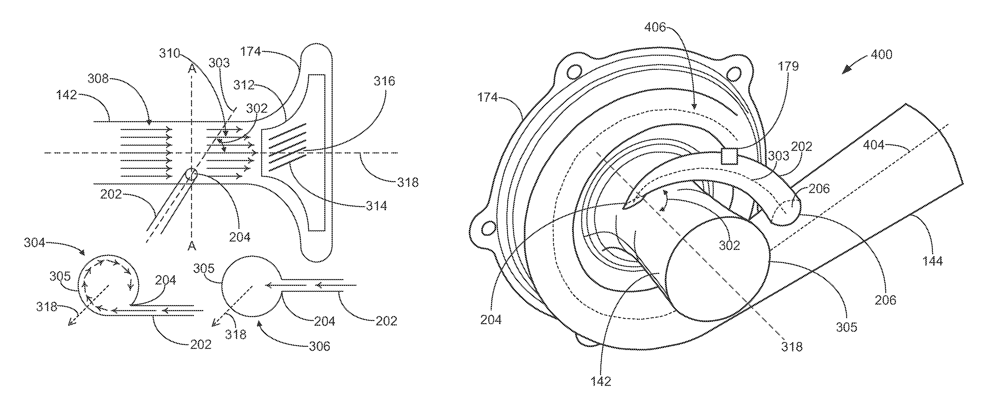
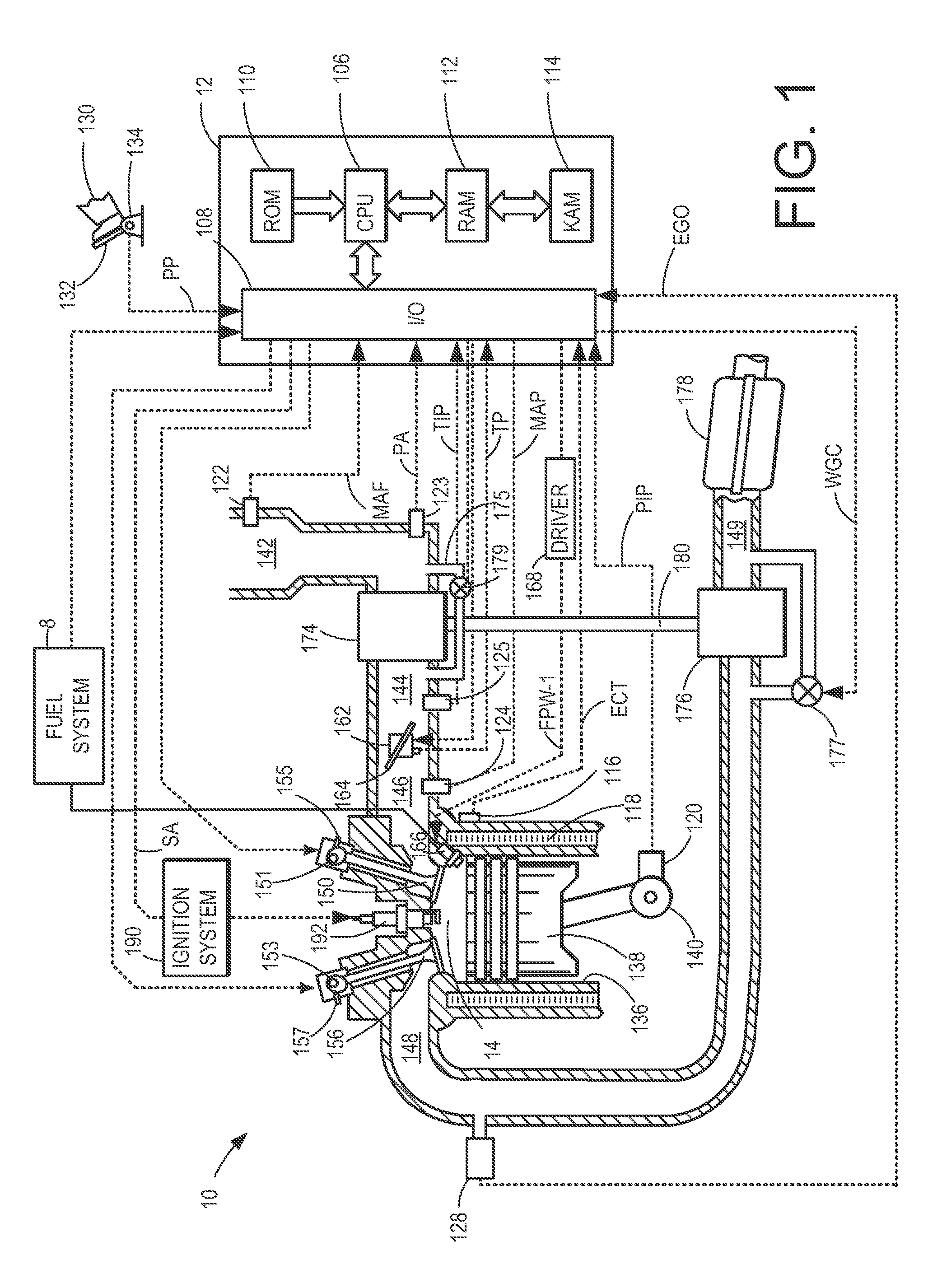
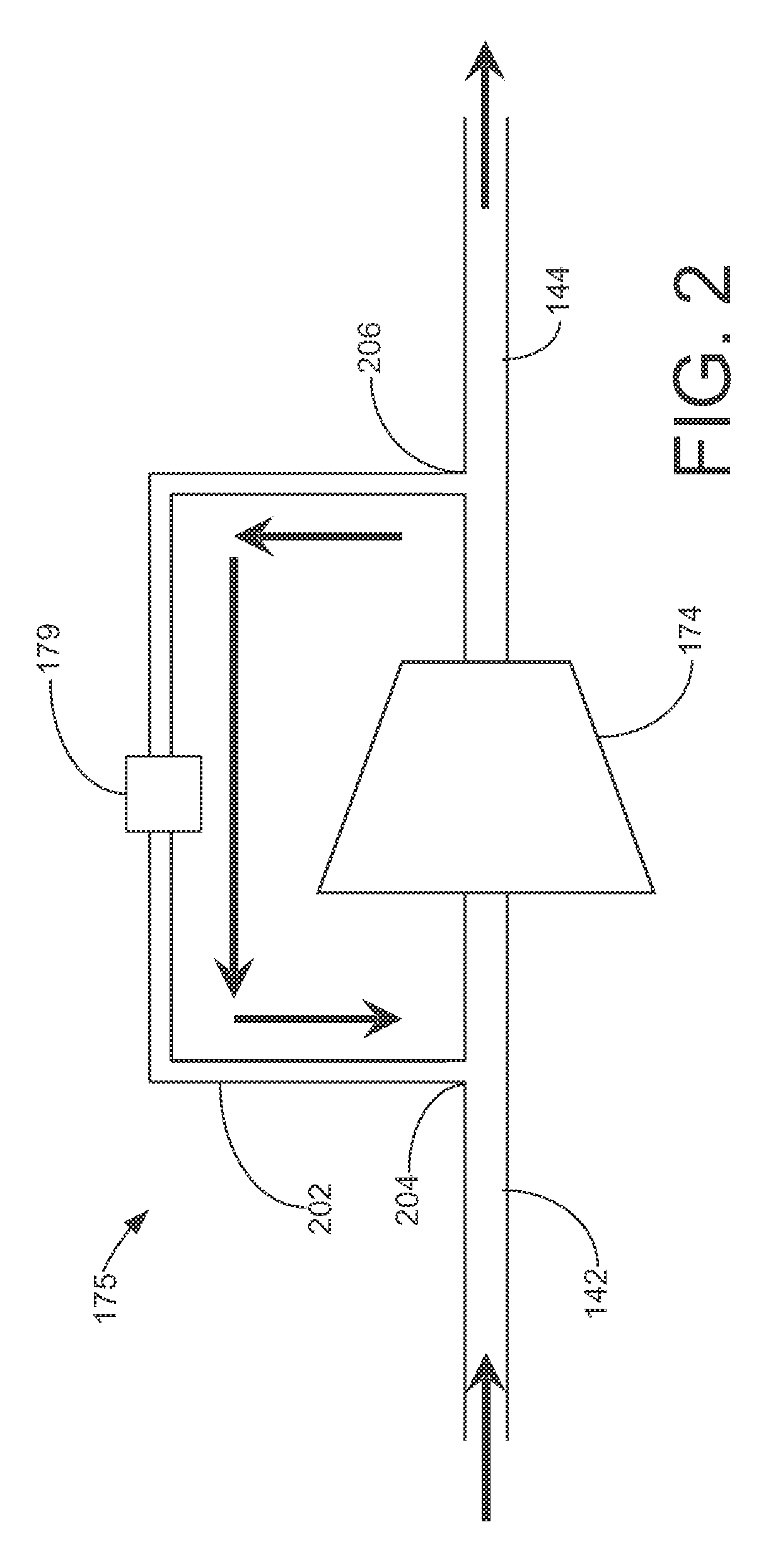
[0012]The following description relates to systems and methods for controlling compressor inlet flow in a turbocharger of an engine, such as the engine shown in FIG. 1. As one example, a compressor bypass conduit, such as shown in FIG. 2, may be used to direct pressurized air from downstream the compressor to the compressor inlet. As another example, a conduit may be used to direct pressurized air from a high pressure source to the compressor inlet, as shown in FIG. 3. The compressor bypass conduit design may be based on various components of the compressor, such as shown in FIG. 3, so that the compressor inlet velocity flow field can be tailored and controlled to increase the efficiency of the compressor rotor, increasing the surge margin of the compressor, reducing low end NVH effects such as tip-in and tip-out whoosh, improving transient response characteristics such as time-to-torque, and minimizing the high end flow loss effects associated intrusive devices, for example.

[0013]F...


PUM


Abstract

Systems and methods for controlling compressor inlet flow in a turbocharger of an engine are described. In one example, a method for controlling a compressor inlet flow of an engine turbocharger system includes: directing air from a high pressure source to an inlet upstream of a compressor wheel via a conduit coupled to the inlet and the high pressure source, where the conduit is obliquely coupled to the inlet.

Description

BACKGROUND AND SUMMARY[0001]Engines may use a turbocharger to increase engine torque / power output density. In one example, a turbocharger may include a compressor and a turbine connected by a drive shaft, where the turbine is coupled to the exhaust manifold side and the compressor is coupled to the intake manifold side. In this way, the exhaust-driven turbine supplies energy to the compressor to increase the pressure in the intake manifold (e.g. boost, or boost pressure) and to increase the flow of air into the engine. The boost may be controlled by adjusting the amount of gas reaching the turbine, such as with a wastegate.[0002]However, when matching a turbocharger to an engine, there is a constant trade-off between low end torque capability limits from surge, and high end performance limited by flow losses and turbine sizing. In order to address these issues, devices such as Inlet Guide Vanes (IGV), compressor housing grooves, and casing treatments can be implemented into the turb...

Claims


Application Information

Patent Timeline
Patent Type & Authority Patents(United States)
IPC IPC(8): F02B33/44F02M25/07F02B37/16F02B37/10
CPCF02B37/16F02B37/10Y02T10/144F04D27/0238F05D2250/51F05D2260/14Y02T10/12
Inventor MIAZGOWICZ, KEITH D.KARIM, AHSANULPAYNE, KEVINCHRISTIAN, ADAM MICHAEL
Owner FORD GLOBAL TECH LLC
Why Eureka
Try Eureka