Separator device
- Summary
- Abstract
- Description
- Claims
- Application Information
AI Technical Summary
Benefits of technology
Problems solved by technology
Method used
Image

Examples
Embodiment Construction
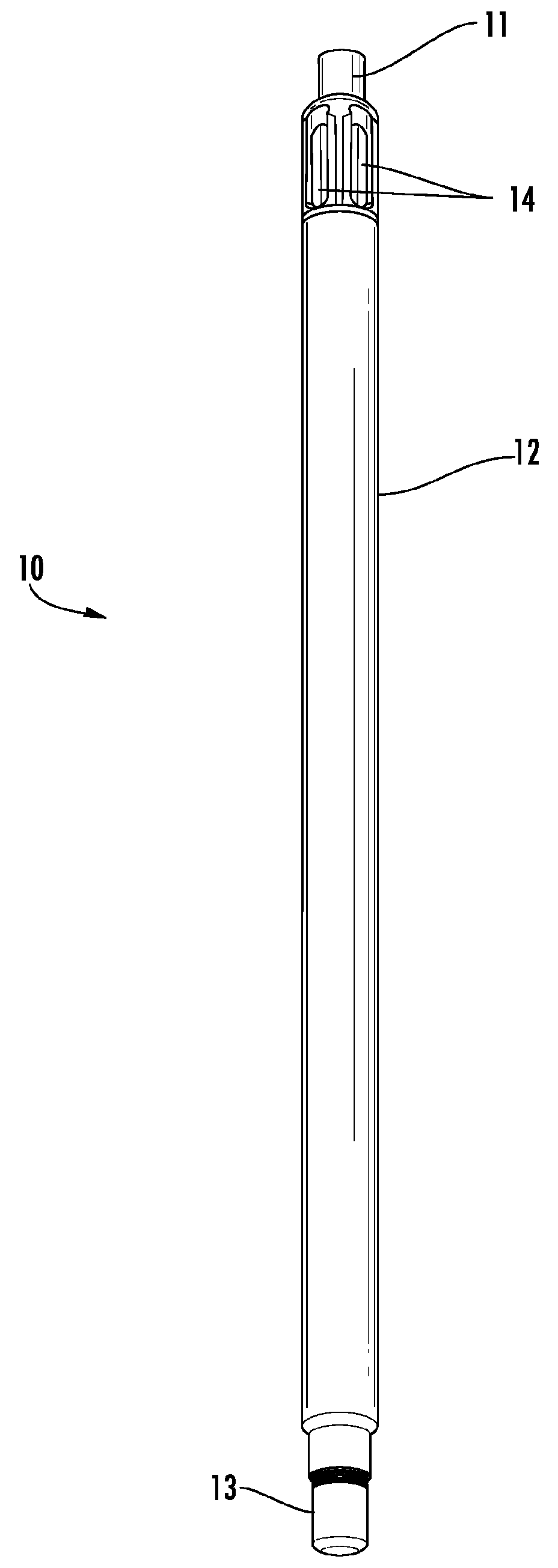
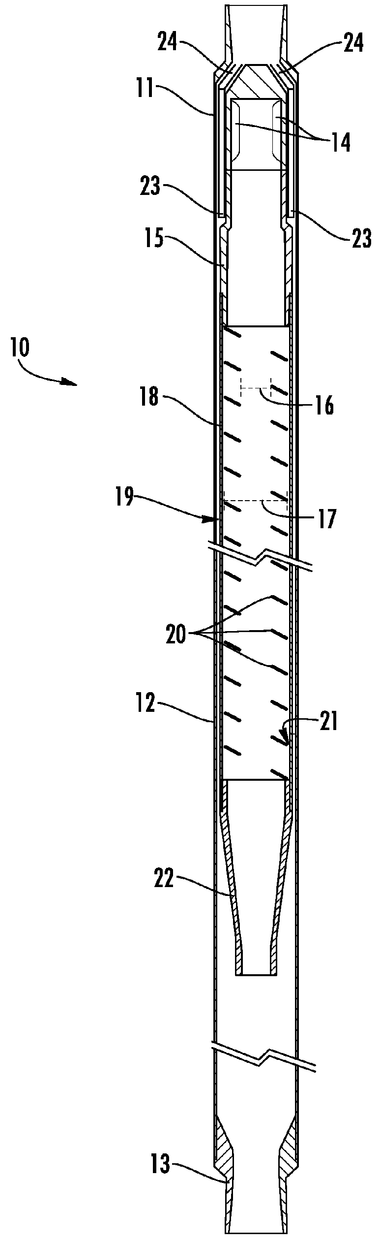
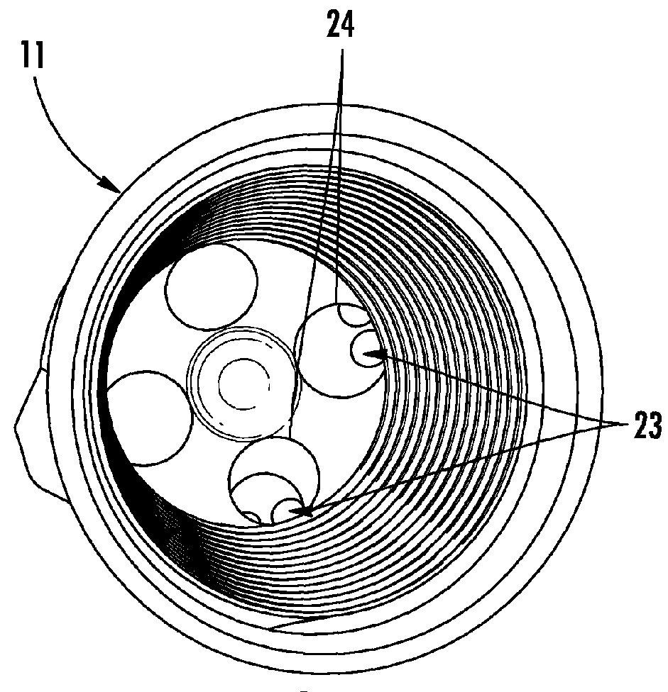
[0031]Referring now to FIGS. 1-11, exemplary embodiments of a separator device 10 in accordance with the present disclosure are illustrated. The separator device 10 according to the present disclosure generally includes an outer tube 12; an inner tube 18 disposed within the outer tube 12; an outer annular space 19 inside the outer tube 12, wherein the outer annular space 19 defines an annular void space formed between the exterior surface of the inner tube 18 and the interior surface of the outer tube 12; and a flighting member 20 disposed within the inner tube 18, wherein the flighting member 20 includes an inside diameter space 16 that defines a cylindrical void space extending through the center portion of the flighting member 20.
[0032]As depicted in FIGS. 1 and 8, the outer tube 12 may define a long unperforated pipe. The outer tube 12 includes a first end, a second end, an interior surface and an exterior surface. The first end and the second end of the outer tube 12 may define...
PUM
| Property | Measurement | Unit |
|---|---|---|
| Centrifugal force | aaaaa | aaaaa |
| Flow rate | aaaaa | aaaaa |
| Diameter | aaaaa | aaaaa |
Abstract
Description
Claims
Application Information
 - Generate Ideas
- Intellectual Property
- Life Sciences
- Materials
- Tech Scout
- Unparalleled Data Quality
- Higher Quality Content
- 60% Fewer Hallucinations
Browse by: Latest US Patents, China's latest patents, Technical Efficacy Thesaurus, Application Domain, Technology Topic, Popular Technical Reports.
© 2025 PatSnap. All rights reserved.Legal|Privacy policy|Modern Slavery Act Transparency Statement|Sitemap|About US| Contact US: help@patsnap.com