Air cooler having a condensation trap and method for air cooler operation

a condensation trap and air cooler technology, applied in the field of air coolers, can solve the problems of reducing air density, reducing air density, increasing the temperature of the intake air, etc., and achieving the effects of reducing emissions, increasing intake air density, and increasing combustion outpu

Active Publication Date: 2016-02-02
FORD GLOBAL TECH LLC
View PDF17 Cites 3 Cited by
  • Summary
  • Abstract
  • Description
  • Claims
  • Application Information

AI Technical Summary

Benefits of technology

[0002]Compressors are used in engine intake systems to increase the density of the intake air. Consequently, the combustion output may be increased, emissions may be decreased, and / or fuel economy may be increased. However, compressing intake air also increases the temperature of the intake air. This increase in air temperature decreases air density, thereby diminishing some of the gains achieved via compression of the intake air. Therefore, air coolers positioned downstream of compressors may be used to decrease the temperature of compressed intake air in boosted engines. Air coolers may also be used in conjunction with other systems in the vehicle such as exhaust gas recirculation (EGR) systems to decrease the temperature of the exhaust gas delivered to the intake system.
[0003]Air coolers, such as charge air coolers, may be designed for specific engine applications. Specifically, the size and geometry of air flow passages in air coolers may be sized for a specific engine or vehicle. When the air coolers are uniquely sized for an engine, the applicability of the air cooler is decreased. For example, if a specified air cooler were used in another engine or vehicle configuration, the engine may experience misfires due to condensation build up caused by the mis-sizing. As a result, combustion efficiency may be decreased. Furthermore, misfires may be exacerbated when the intake air has a high humidity, a large amount of torque is requested by the vehicle operation (e.g., open throttle conditions), and / or during a downshift in a transmission.
[0005]The condensate containment shelf enables condensate to be accumulated during certain operating conditions. Additionally, the condensate restriction reduces the flowrate of the accumulated condensate into the outlet port. As a result, flowrate of condensate into downstream cylinders is reduced, thereby increasing combustion efficiency and reducing emissions. Furthermore, the likelihood of misfires caused by an excess amount of moisture in the cylinders during combustion is also reduced.

Problems solved by technology

However, compressing intake air also increases the temperature of the intake air.
This increase in air temperature decreases air density, thereby diminishing some of the gains achieved via compression of the intake air.
For example, if a specified air cooler were used in another engine or vehicle configuration, the engine may experience misfires due to condensation build up caused by the mis-sizing.
As a result, combustion efficiency may be decreased.
Furthermore, misfires may be exacerbated when the intake air has a high humidity, a large amount of torque is requested by the vehicle operation (e.g., open throttle conditions), and / or during a downshift in a transmission.

Method used


Image

  • Air cooler having a condensation trap and method for air cooler operation
  • Air cooler having a condensation trap and method for air cooler operation
  • Air cooler having a condensation trap and method for air cooler operation

Examples


Embodiment Construction

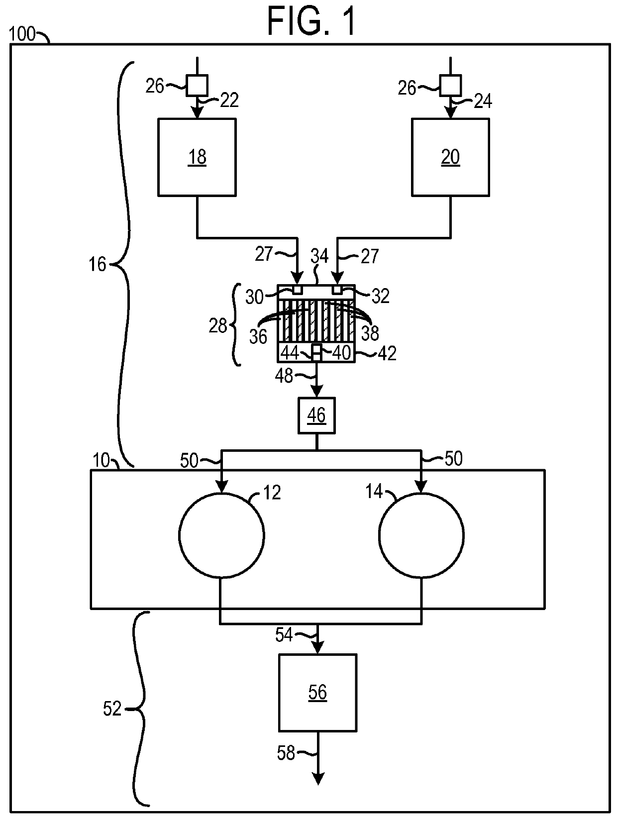
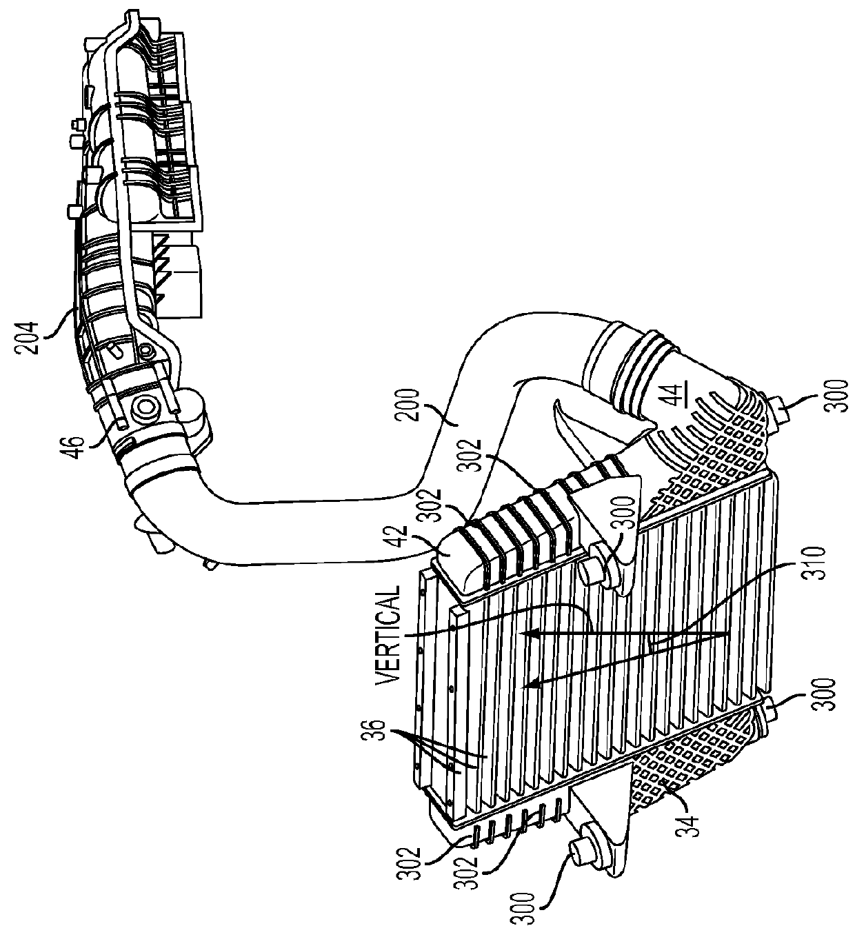
[0015]An air cooler having a condensate trap is described herein. The condensate trap is positioned in an outlet manifold of the air cooler, the condensate trap includes a condensate containment shelf positioned to receive condensate formed in cooling passages upstream of the outlet manifold in the air cooler. The condensate containment shelf enables condensate formed in the cooling passages to be flowed into a desired region of the outlet manifold. Specifically, in one example the condensate containment shelf may be arranged at a non-perpendicular angle with regard to a vertical axis. In this way, the condensate may be passively directed to a lower portion of the outlet manifold. The condensate trap further includes a condensate restriction reducing the flow of condensate into an outlet port of the outlet manifold. The condensate restriction may be formed by an outlet port housing and the condensate containment shelf. The condensate restriction reduces the flowrate of condensate in...


PUM


Abstract

A condensate trap upstream of an engine cylinder is provided. The condensate trap includes a condensate containment shelf positioned within an outlet manifold of an air cooler, above a lower side of the outlet manifold, and extending from a first lateral side of the outlet manifold to a second lateral side of the outlet manifold, the condensate containment shelf and a outlet port housing forming a condensate restriction in direct fluidic communication with an outlet port of the outlet manifold.

Description

FIELD[0001]The present disclosure relates to an air cooler having a condensate trap in an intake system of on engine.BACKGROUND AND SUMMARY[0002]Compressors are used in engine intake systems to increase the density of the intake air. Consequently, the combustion output may be increased, emissions may be decreased, and / or fuel economy may be increased. However, compressing intake air also increases the temperature of the intake air. This increase in air temperature decreases air density, thereby diminishing some of the gains achieved via compression of the intake air. Therefore, air coolers positioned downstream of compressors may be used to decrease the temperature of compressed intake air in boosted engines. Air coolers may also be used in conjunction with other systems in the vehicle such as exhaust gas recirculation (EGR) systems to decrease the temperature of the exhaust gas delivered to the intake system.[0003]Air coolers, such as charge air coolers, may be designed for specifi...

Claims


Application Information

Patent Timeline
Patent Type & Authority Patents(United States)
IPC IPC(8): F02B29/04F25D21/14F02B33/00F02M15/00
CPCF25D21/14F02B29/0456F02B29/0468Y02T10/121Y02T10/146Y10T137/5762Y02T10/12
Inventor PALM, JIM RAYMONDCOCKERILL, CHARLES ALLENYAMADA, SHUYA SHARK
Owner FORD GLOBAL TECH LLC
Why Eureka
Try Eureka