Transverse flux electrical motor

a technology of electrical motors and fluxes, applied in the direction of dynamo-electric machines, electrical apparatus, magnetic circuit shapes/forms/construction, etc., can solve the problems of movable winding needs, limited speed, friction, acoustic noise,

Active Publication Date: 2016-02-02
YASKAWA EURO TECH
View PDF13 Cites 8 Cited by
  • Summary
  • Abstract
  • Description
  • Claims
  • Application Information

AI Technical Summary

Problems solved by technology

Some of the disadvantages however include limits in speed, and relatively high vibration, friction, and acoustic noise.
These linear motors have a disadvantage however in that the movable winding needs to be connected by cable to the driver current of the motor.
In order to avoid deterioration of the connecting cables, a cable arrangement that is costly and complicated is usually required.
Further, the cable connection creates mechanical friction and perturbations that affect the smoothness of the motor movement.
A problem with this configuration however is that the windings and magnetic core are extended along the full length of the linear motor, which makes the motor relatively heavy and expensive.
Further, these motors have low efficiency since only the small section of the winding that is in front of the moving element is active.
The attraction force acts as a constraint on movement, requiring additional current input to overcome, which further reduces motor efficiency.
However, when these motors operate at high speed, the rotating magnets on the rotor become subject to a strong centrifugal force.
This creates a risk that the magnets might dislodge and fly off.
In order to reduce this risk, costly design features are needed.
A problem with IPM motors is that they include a “reluctance torque” which must be compensated by the electronic drive in order to maintain a constant torque for a given current amplitude at variable rotation angles.
This design accordingly limits the maximum torque available to a lower value, and degrades the linear relationship between motor current and torque output.
Accordingly, in order to obtain the desired high torque, the direct drive motor becomes relatively large and heavy.
Some common disadvantages of TFM's include low power factor and complex construction with three-dimensional magnetic fields.
The use of lamination in TFM's is complicated, so that sometimes the costly soft magnetic composite materials are required.

Method used


Image

  • Transverse flux electrical motor
  • Transverse flux electrical motor
  • Transverse flux electrical motor

Examples


Embodiment Construction

[0045]Reference will now be made in detail to embodiment(s) of the present invention, examples of which are illustrated in the accompanying drawings, wherein like reference numerals refer to the like elements throughout. Individual drawings may have like elements or sections corresponding to other drawings. These components are in some instances re-introduced and re-numbered in association with the particular drawing in which they appear. The embodiment(s) is / are described below to explain the present invention by referring to the figures.

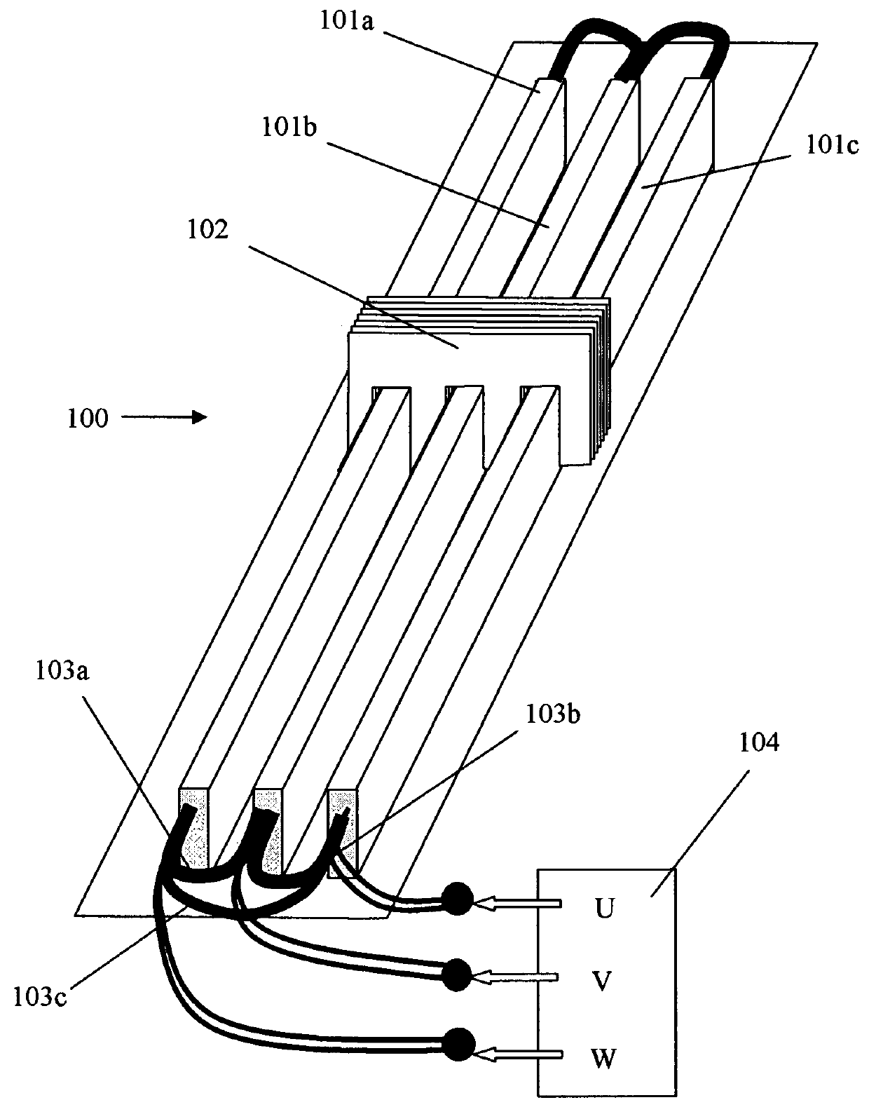
[0046]Referring now to FIG. 1, there is shown a perspective view of a three phase linear motor 100 consistent with an embodiment of the present invention. Three linear tracks, 101a, 101b, and 101c, are disposed parallel to one another, and a carriage 102 made of magnetic laminar material is moveable along these three tracks. For drawing clarity the necessary mechanical arrangement is not shown, as it may be made using any type of linear bearing. Th...


PUM


Abstract

A transverse flux electrical motor to produce motion from an input electric current, the electrical motor comprising: a static element having a plurality of magnets arranged in at least two rows and defining a path of movement; a magnetizable movable element having at least two openings, each opening being sized and shaped to receive a magnet from one of the rows of magnets, the movable element being movable along the path of movement such that the magnets of each row pass through one of the openings; and a plurality of windings positioned adjacent to the movable element, to receive the electric current and produce a magnetic flux circuit in the movable element and a force on the movable element in the direction of the path of movement; wherein the magnetic flux circuit in the movable element is transverse to the direction of force on the movable element.

Description

[0001]The present application is based on and claims priority of U.S. Provisional Patent Application No. 61 / 238,224, filed Aug. 31, 2009.BACKGROUND OF THE INVENTION[0002]1. Technical Field[0003]Embodiments of the present invention relate generally to electrical motors and, more particularly, but not exclusively, to transverse flux machines in which the electromagnetic force vector is perpendicular to the magnetic flux lines.[0004]2. Description of Related Art[0005]Linear motion systems are in common use in industry, with different systems available to handle a variety of applications.[0006]One type of system uses a ball and screw arrangement, in which the ball screw is rotated by a static rotary motor. An advantage of this arrangement is that the electric cables that drive the system are statics, and therefore may be fixed to the main body of the machine. Some of the disadvantages however include limits in speed, and relatively high vibration, friction, and acoustic noise.[0007]Wher...

Claims


Application Information

Patent Timeline
Patent Type & Authority Patents(United States)
IPC IPC(8): H02K1/17H02K41/03H02K21/44
CPCH02K41/03H02K21/44H02K2201/12
Inventor VILLARET, YVES
Owner YASKAWA EURO TECH
Why Eureka
Try Eureka