Ionization probe

a technology of ionization probe and probe body, which is applied in the field of ionization probe, can solve the problems of increasing and achieve the effects of reducing the size of the ionization probe itself, increasing the ionization efficiency, and promoting the gasification of solvent in the sample drop

Active Publication Date: 2016-02-09
SHIMADZU CORP
View PDF5 Cites 3 Cited by
  • Summary
  • Abstract
  • Description
  • Claims
  • Application Information

AI Technical Summary

Benefits of technology

[0024]In the ionization probe of the present invention, assist gas is supplied for example from an external assist gas supply source through a suitable pipe into an annular assist gas channel provided at the tip part of the nozzle and assist nozzle. The supplied assist gas is heated by a heater in the assist gas channel and reaches a high temperature. The high temperature assist gas flows through the gas outlet of the assist gas channel into the assist gas nozzle, and is discharged through the open part provided around the nozzle tip. This high temperature assist gas stream proceeds substantially in a direction so as to surround the sample drop spray stream from the nozzle tip. Thus, the solvent in the sample drops is efficiently gasified by the heat of the assist gas. Furthermore, the spreading of the sample drop spray stream and the ions generated from those drops is suppressed.
[0025]In the ionization probe of the present invention, the heat source, including the heater and the channel through which high temperature assist gas passes, is provided only around the tip part of the nozzle which discharges sample drops into the ionization chamber, for example. Thus, the probe base part located directly at the opposite end of the ionization probe from the nozzle tip is positioned away from the heat source, and this base part is not prone to being heated and can be easily thermally insulated.
[0029]The temperature of assist gas in the assist gas channel is higher closer to the gas outlet, and the assist gas nozzle is provided at a position near that gas outlet, so assist gas which has reached a high temperature is discharged from the open part of the assist gas nozzle without reduction in temperature. Furthermore, the assist gas nozzle is at a location far away from the gas inlet of the assist gas channel which has relatively low temperature, and thus is not readily affected by the low temperature assist gas, so the assist gas nozzle is not readily cooled. Consequently, it becomes possible to efficiently utilize the heat produced by the heater and discharge high temperature assist gas from the opening of the assist gas nozzle.
[0034]With the ionization probe of the present invention, when it is mounted in an atmospheric pressure ionization mass spectrometer, the probe base part which can normally be touched by the user is located away from the heat source, making it possible to keep the probe base part at a safe temperature without using a large thermal insulation space or bulky thermal insulation material. Furthermore, since such large thermal insulation space and bulky thermal insulation material is not necessary, the size of the ionization probe itself can be reduced, which is advantageous for miniaturization of the ionization probe.
[0035]In the ionization probe of the present invention, with the preferable configurations described above, high temperature assist gas can be stably discharged from the assist gas nozzle, making it possible to promote the gasification of solvent in the sample drops and increase the ionization efficiency. Furthermore, the heat of the heater can be efficiently used, so for example, the amount of heating power necessary for discharging assist gas at the same temperature can be reduced, which is advantageous for reducing power consumption.

Problems solved by technology

However, with either of these thermal insulation methods, the size of the ionization probe inevitably increases.

Method used


Image

  • Ionization probe
  • Ionization probe
  • Ionization probe

Examples


Embodiment Construction

[0040]An example of embodiment of the ionization probe of the present invention and an LC / MS in which the ionization probe of this example of embodiment has been installed will be described below with reference to the appended drawings.

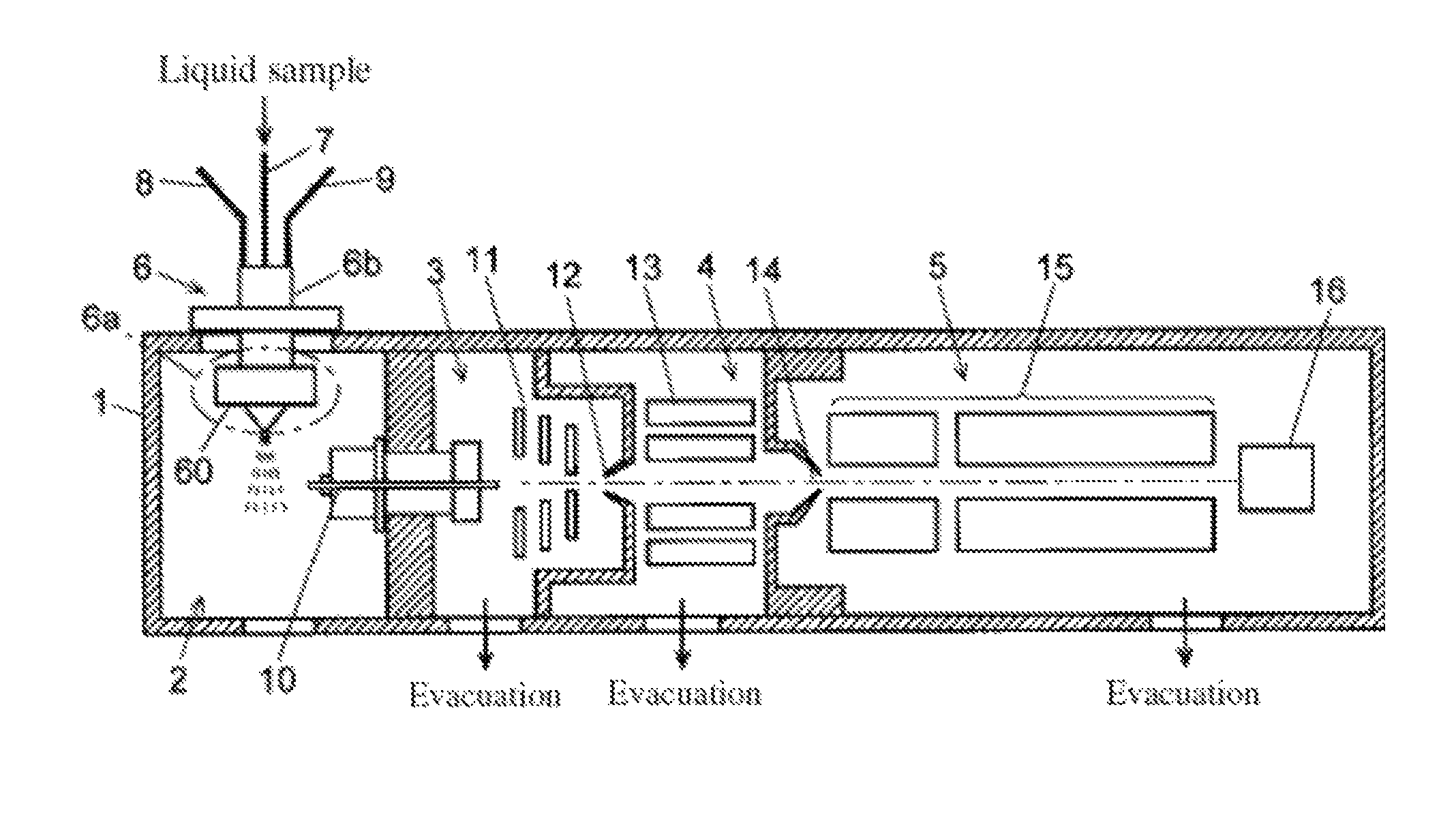
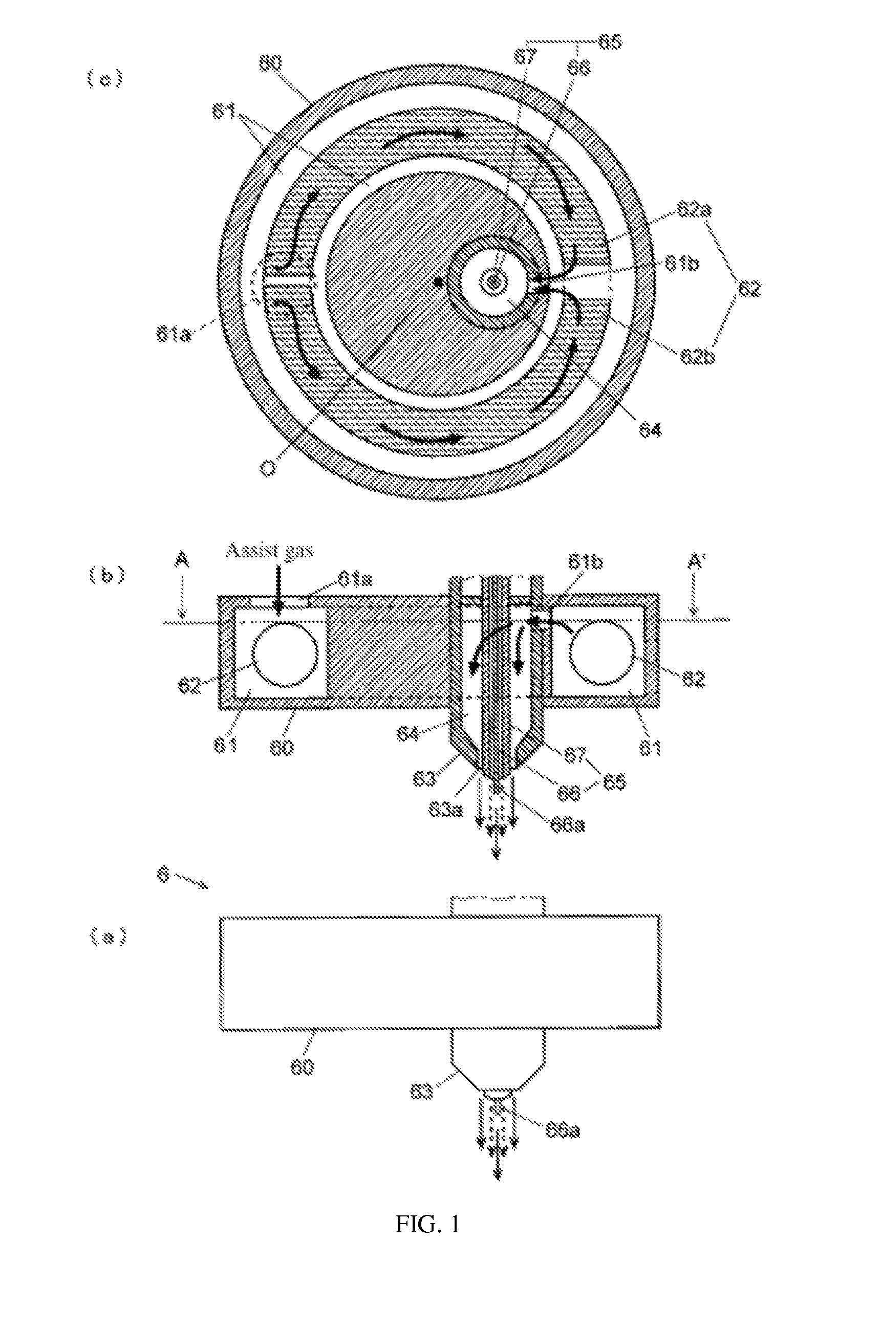
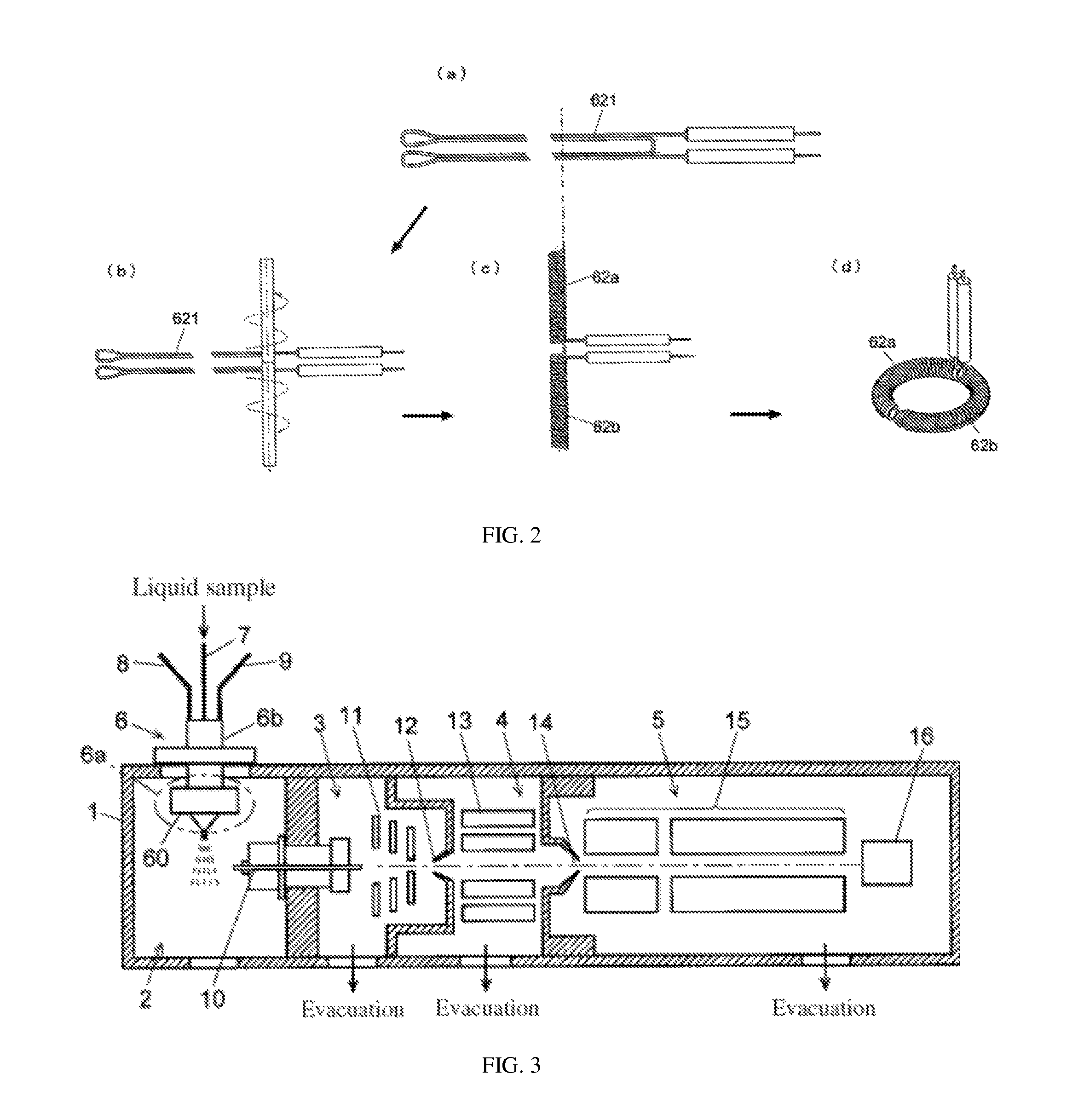
[0041]FIG. 1 is an external view of the main parts and an approximate cross-sectional diagram of the ESI ionization probe of the present example of embodiment, and FIG. 3 is a simplified diagram of an atmospheric pressure ionization mass spectrometer in which this ionization probe has been installed.

[0042]First, referring to FIG. 3, the atmospheric pressure ionization mass spectrometer will be described. This atmospheric pressure ionization mass spectrometer comprises, inside chamber 1, an ionization chamber 2, a first intermediate vacuum chamber 3, a second intermediate vacuum chamber 4 and an analytical chamber 5. An ESI ionization probe 6 which ionizes components in a liquid sample is arranged in ionization chamber 2, ion guides 11 and 13 which foc...


PUM


Abstract

In the ionization probe, an assist gas nozzle, coaxial with a nozzle, is provided around a nozzle that discharges a liquid sample. A housing inside which is formed an annular assist gas channel is provided around the assist gas nozzle. A gas inlet for introducing gas into the assist gas heating channel and gas outlet for feeding gas from channel to assist gas nozzle are provided at opposite locations across the center of the channel. Gas introduced into the assist gas heating channel is heated by a substantially annular heater, and high temperature gas is discharged through gas discharge hole of the assist gas nozzle. The heater and the channel through which high temperature gas flows are arranged solely at the tip part of the ionization probe, so thermal insulation of the probe base part can be easily accomplished.

Description

[0001]This application claims priority from Japan Patent Application No. 2013-79374, filed Aug. 30, 2013, the entire disclosure of which is herein incorporated by reference.TECHNICAL FIELD[0002]The present invention relates to an ionization probe for atomizing a liquid sample inside an ionization chamber and ionizing components in the sample; more specifically, the invention relates to an ionization probe used with ion sources in an atmospheric pressure ionization mass spectrometry apparatus which ionizes components in a liquid sample in a substantially ambient pressure atmosphere and performs mass spectrometry on the generated ions.BACKGROUND ART[0003]A liquid chromatography / mass spectrometry apparatus (LC / MS) generally comprises a liquid chromatograph which separates components in a sample in the time direction, and an atmospheric pressure ionization mass spectrometer which ionizes, under a substantially ambient pressure atmosphere, the components in the liquid sample eluted from ...

Claims


Application Information

Patent Timeline
Patent Type & Authority Patents(United States)
IPC IPC(8): H01J49/26B05B9/00
CPCB05B9/002H01J49/0445H01J49/0477G01N30/7246G01N30/7266
Inventor NAKANO, TOMOHITO
Owner SHIMADZU CORP
Why Eureka
Try Eureka