Thermal storage system, thermal storage container, thermal storage device using thermal storage container, and warm air device using thermal storage device

A heat storage system and heat storage technology, applied in heat storage equipment, indirect heat exchangers, heat exchanger types, etc., can solve the problems of reduced heat utilization, complicated piping structure, and difficulty in heat storage.

Inactive Publication Date: 2019-04-16
FURUKAWA ELECTRIC CO LTD
View PDF6 Cites 0 Cited by
  • Summary
  • Abstract
  • Description
  • Claims
  • Application Information

AI Technical Summary

Problems solved by technology

[0004] However, in the heat storage container 6 of Patent Document 1, it is necessary to separately provide the reaction flow path 64 for supplying water vapor and the heat exchange flow path 66 for supplying the heat exchange medium, so there is a problem that the piping configuration is complicated.
In addition, due to the complexity of the piping structure, the amount of chemical heat storage material 62 that can be mounted on the heat storage container 6 decreases, so there is a problem that the heat utilization per unit volume of the heat storage container 6 (heat storage density) decreases.
[0005] In addition, the temperature (heat storage temperature) required for heat storage of chemical heat storage materials is as high as 350°C or higher, and there is a problem that it is difficult to store heat depending on the location where the heat storage container is placed.

Method used


Image

  • Thermal storage system, thermal storage container, thermal storage device using thermal storage container, and warm air device using thermal storage device
  • Thermal storage system, thermal storage container, thermal storage device using thermal storage container, and warm air device using thermal storage device
  • Thermal storage system, thermal storage container, thermal storage device using thermal storage container, and warm air device using thermal storage device

Examples


Embodiment Construction

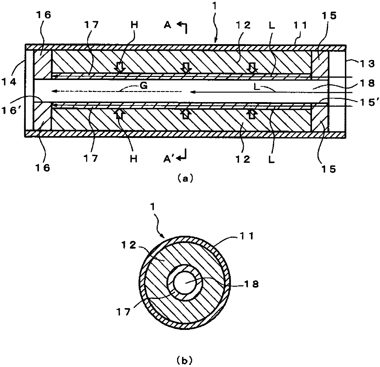
[0068] Hereinafter, the thermal storage container which concerns on 1st Embodiment of this invention is demonstrated using drawing. Such as figure 1 As shown in (a), the heat storage container 1 according to the first embodiment includes a cylindrical body 11 which is a tubular body with both ends opened, and an adsorbent 12 arranged inside the cylindrical body 11 . In addition, the heat storage container 1 includes: a first cover 15, which is arranged adjacent to the one end 13 side of the cylindrical body 11 of the adsorbent 12, and is made of a porous body; The other end portion 14 side of the cylindrical body 11 is adjacently disposed and is made of a porous body; The inner side of 12 is arranged adjacent to a diffusion layer for transporting liquid, and has a capillary structure.

[0069] Such as figure 1 As shown in (b), the cross section in the radial direction of the cylindrical body 11 is circular. In addition, the adsorbent 12 is a form in which powder is compr...


PUM


Abstract

Provided are a thermal storage system, thermal storage container, and thermal storage device using said thermal storage container that enable the amount of heat generated and amount of heat transported to be enhanced with a simple configuration. The thermal storage system uses a thermal storage container that comprises: a tubular body; an adsorbent material that is housed in the tubular body, generates heat through adsorption of a substance to be adsorbed, and absorbs heat through desorption of the subject to be adsorbed; and a channel penetrating through the tubular body in a long-axis direction. In the system, included is a diffusion layer for diffusing a liquid-phase substance to be adsorbed from the channel to the adsorbent material; the substance to be adsorbed is transported to the channel; the substance to be adsorbed is transported to the diffusion layer; some of the substance to be adsorbed having been transported to the diffusion layer is adsorbed onto the adsorbent material;the adsorbent material releases heat; and the remainder of the substance to be adsorbed is evaporated by the heat and becomes a heat transport fluid.

Description

technical field [0001] The present invention relates to a thermal storage container using an adsorbent capable of utilizing heat released and absorbed when an adsorbent (such as zeolite) adsorbs an adsorbate (such as water, etc.) and a thermal storage device including the thermal storage container. The function of absorbing heat when the adsorbate (for example, water, etc.) desorbs, repeats heat generation and heat storage. Background technique [0002] In recent years, studies have been made on the storage and utilization of waste heat in industrial equipment and the like, particularly heat storage systems for storing and using waste heat obtained from engines of automobiles. [0003] For this, as Figure 8 As shown, a heat storage container 6 is proposed, wherein a chemical heat storage material composite including a chemical heat storage material 62 of powder and a foaming expansion material 63 arranged adjacent to the chemical heat storage material 62 is accommodated in ...

Claims


Application Information

Patent Timeline
Patent Type & Authority Applications(China)
IPC IPC(8): F28D20/00F25B17/08F28D15/02F28D15/04F28D15/06
CPCF25B17/08F28D7/106F28D15/043F28D15/046F28D20/003F28D2020/0017F28F2255/18Y02B30/00Y02B30/62Y02E60/14Y02A30/27F28D15/0233F28D15/06F28D2021/0019
Inventor 近泽启子木村裕一田中贤吾岛田守
Owner FURUKAWA ELECTRIC CO LTD
Why Eureka
Try Eureka