Control of A/F ratio at cut-out speed

a technology of a/f ratio and control of a/f ratio, which is applied in the direction of electric control, speed sensing governor, instruments, etc., can solve the problems of increased size and weight, drastic increase in costs, and difficult use of technology for mounting reasons and also for cost-efficiency and operational safety reasons, so as to reduce problems

Active Publication Date: 2016-02-09
HUSQVARNA AB
View PDF9 Cites 10 Cited by
  • Summary
  • Abstract
  • Description
  • Claims
  • Application Information

AI Technical Summary

Problems solved by technology

However, for consumer products, such as power saws, lawn mowers, and similar products, this technology is difficult to use for mounting reasons and also for cost-efficiency and operational-safety reasons.
For instance, in a power saw, a system with sensors and probes would result in increased size and weight as well as a drastic rise in costs and possibly also cause operational safety problems.
Further the sensor or the probe often requires a reference having completely pure oxygen, which is a situation that it is practically impossible to achieve in some engines, for instance the motors of power saws.
Expected future legislation with respect to CO-emissions from small IC engines may make it difficult to use manually adjusted carburetors.
However, the engine control method of EP 0 715 686 B1 is somewhat slow and also requires the product to be ran under a load when fine-tuning the A / F ratio.
Some machines, such as bush cutters, are not usually operated under constant load and are could thus be difficult or take even longer time to fine-tune with the method of EP 0 715 686 B1.
However, it is sometimes desirable to find an optimal A / F ratio also when not being able to adjust under a load.

Method used


Image

  • Control of A/F ratio at cut-out speed
  • Control of A/F ratio at cut-out speed
  • Control of A/F ratio at cut-out speed

Examples


Embodiment Construction

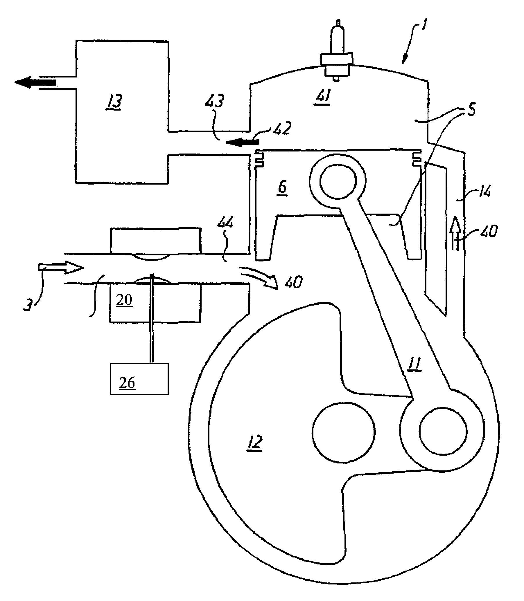
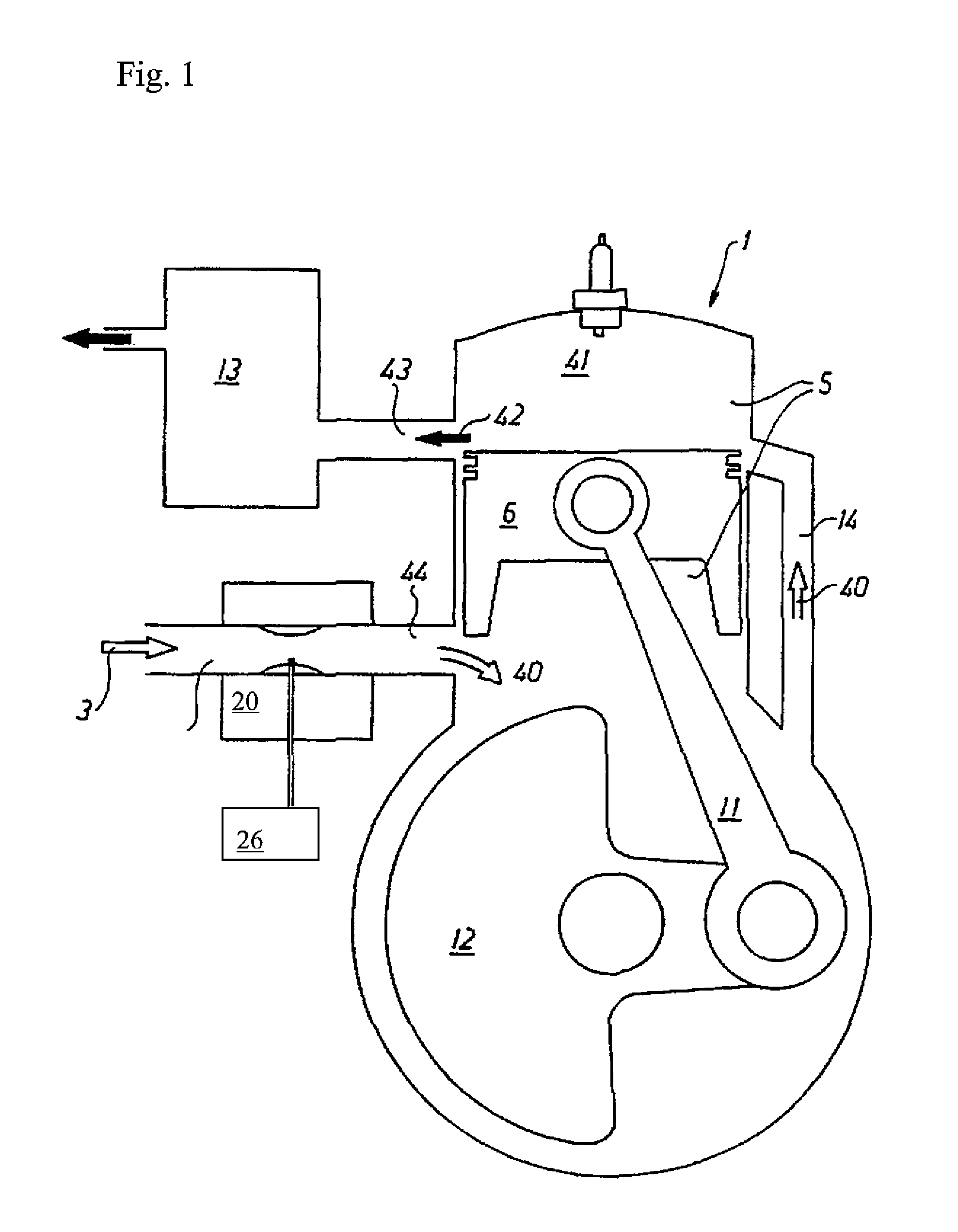
[0019]In the schematically illustrated drawing FIG. 1 numeral reference 1 designates an internal combustion engine of a two-stroke type. It is crank case scavenged, i.e. a mixture 40 of air 3 and fuel from a fuel supply system 20 (e.g. a carburetor or a low pressure fuel injection system) is drawn to the engine crank house. From the crank house, the mixture is carried through one or several scavenging passages 14 up to the engine combustion chamber 41. The chamber is provided with a spark plug igniting the compressed air-fuel mixture. Exhausts 42 exit through the exhaust port 43 and through a silencer 13. All these features are entirely conventional in an internal combustion engine and for this reason will not be described herein in any closer detail. The engine has a piston 6 which by means of a connecting rod 11 is attached to a crank portion 12 equipped with a counter weight. In this manner the crank shaft is turned around. In FIG. 1 a piston 6 assumes an intermediate position wh...


PUM


Abstract

The invention concerns a method for controlling at least one of a fuel supply and an air supply to an internal combustion engine (1), in a fuel supply section thereof, such that an A / F-ratio is adjusted automatically to a desired level. Moreover, the method is activated at a speed close to a cut-out speed threshold (52) where the engine speed will fluctuate around the threshold (52) and the method comprises the steps of:receiving engine speed data on rotational speed from the engine (1),briefly changing the A / F ratio,comparing engine speed data that are essentially unaffected by the brief change to engine speed data that are affected by the brief change to evaluate the impact on the engine speed fluctuation resulting from the brief change,adjusting the A / F ratio in the same direction as the brief change if the engine speed data affected by the brief change indicates an increase in acceleration after combustion / s, andadjusting the A / F ratio in the opposite direction to the brief change if the engine speed data affected by the brief change indicates a decrease in acceleration after combustion / s.

Description

TECHNICAL FIELD[0001]The subject invention concerns a method and a device for controlling the supply of fuel and / or air to an internal combustion engine in its fuel supply section, such as the carburetor or the fuel-injection system, to ensure that its mixture ratio is automatically adjusted to the desired level at cut out speed range.BACKGROUND OF THE INVENTION[0002]In all internal combustion engines, IC engines, the air / fuel ratio is of utmost importance for the engine function. Usually the air / fuel ratio is referred to as the A / F-ratio, A and F signifying respectively air and fuel. In order to achieve a satisfactory combination of low fuel consumption, low exhaust emissions, good runability and high efficiency the A / F-ratio must be maintained within comparatively narrow limits.[0003]The requirements that exhaust emissions from the IC engine to be kept low are becoming increasingly stricter. In the case of car engines these requirements have led to the use of exhaust catalysers an...

Claims


Application Information

Patent Timeline
Patent Type & Authority Patents(United States)
IPC IPC(8): F02D41/04F02D31/00F02D41/14F02P9/00
CPCF02D41/04F02D31/007F02D41/1497F02P9/005F02D31/009F02D41/2454F02D35/0053F02D2200/1012F02D2700/02
Inventor LARSSON, MIKAEL
Owner HUSQVARNA AB
Why Eureka
Try Eureka