Energy efficiency ratio meter for direct expansion air-conditioners and heat pumps

a technology of energy efficiency ratio and meter, which is applied in the direction of measuring using digital techniques, lighting and heating apparatus, instruments, etc., can solve the problems of increasing the operating cost, increasing the power consumption, and lowering the capacity of the system, etc., to achieve rapid and direct evaluation of the energy efficiency performance of any operating unit, maximize eer, and reduce the effect of labor intensity

Active Publication Date: 2016-02-16
ADVANTEK CONSULTING ENG
View PDF23 Cites 16 Cited by
  • Summary
  • Abstract
  • Description
  • Claims
  • Application Information

AI Technical Summary

Benefits of technology

[0009]The invention provides a genuine, accurate and practical measurement of the EER of any operating DX cooling, refrigeration, or heating unit, expressed in the standard units of cooling capacity per unit of energy use (Btuh per Watt, or MBH per kW) and as COP. The preferred embodiment is a portable service instrument that can be deployed as an enhancement of, or alternative to standard refrigeration system analyzers, which virtually every HVAC&R service technician is adept at using. Accurate, direct, standard EER and COP measurements are clearly displayed, allowing a technician to immediately appraise the operating efficiency of any unit. The preferred embodiment has standard Schrader refrigerant pressure connections and clamp-on temperature sensors, a clamp-on refrigerant flow rate sensor, and clamp-on electric voltage and current sensors. As a hand-held service instrument, the preferred embodiment enables a field service technician to quickly and directly evaluate the energy efficiency performance of any operating unit, adjust refrigerant level, and perform other indicated service actions as needed to maximize EER without special training or knowledge. And, it enables faster and more accurate evaluation of the energy savings obtainable via replacement with new equipment.

Problems solved by technology

Significant degradation of the air-conditioner, refrigerator, or heat pump components over time, such as refrigerant loss, compressor wear, or fouled heat exchangers, increase the operating cost by lowering the capacity of the system and / or increasing the power consumption.
Measuring the EER, COP and JEER of systems based on the vapor compression cycle is difficult, more so while operating in a field environment rather than a test laboratory.
An accurate heat absorption measurement for these systems is quite complex and requires measurement of the mass flow rate of fluid through the heat exchanger along with enthalpies entering and leaving the heat exchanger.
Consequently, the effects of degradation, such as a worn compressor or a change in oil properties, under typical field conditions on the primary system components and the actual operating EER and COP is largely missed by the prior art.
The prior art methods and devices do not result in an EER or an IEER measurement that is directly comparable against measurements made at different loads, evaporating or condensing temperatures of the same system over time, nor against other systems, nor against published standard efficiency ratings; rather the prior art measurements are relativistic not absolute values and thus application is mostly limited to before versus after comparisons of a certain system operating under the load conditions at a particular time.
(U.S. Pat. No. 4,510,576) relies on stored motor loss tables and compressor manufacturer data, and thus cannot take into account the degradation in compressor performance over time versus the performance of a new, laboratory tested compressor.
(U.S. Pat. No. 6,701,725) does not make an actual measurement of energy efficiency, rather, it relies upon manufacturer's compressor performance data to make an indirect estimate of energy efficiency, and thus does not take into account real versus rated compressor performance degradation.
A method by Mowris (U.S. Pat. No. 8,583,384) makes only a relative estimate of the improvement in energy efficiency and does not provide an absolute measurement of energy efficiency, rather, it relies on temperature differences relative to standard tables to infer a diagnosis.

Method used


Image

  • Energy efficiency ratio meter for direct expansion air-conditioners and heat pumps
  • Energy efficiency ratio meter for direct expansion air-conditioners and heat pumps
  • Energy efficiency ratio meter for direct expansion air-conditioners and heat pumps

Examples


Embodiment Construction

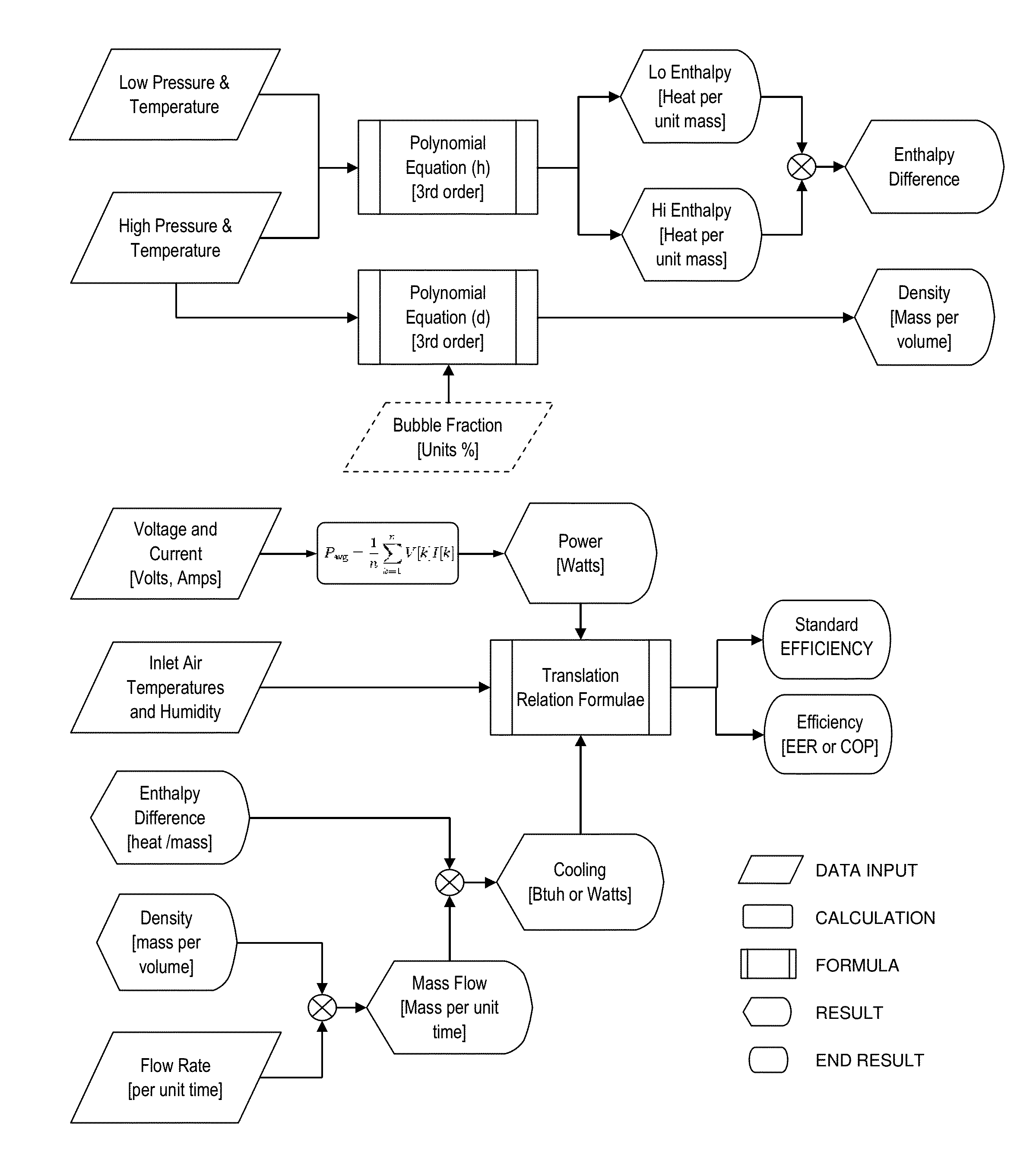
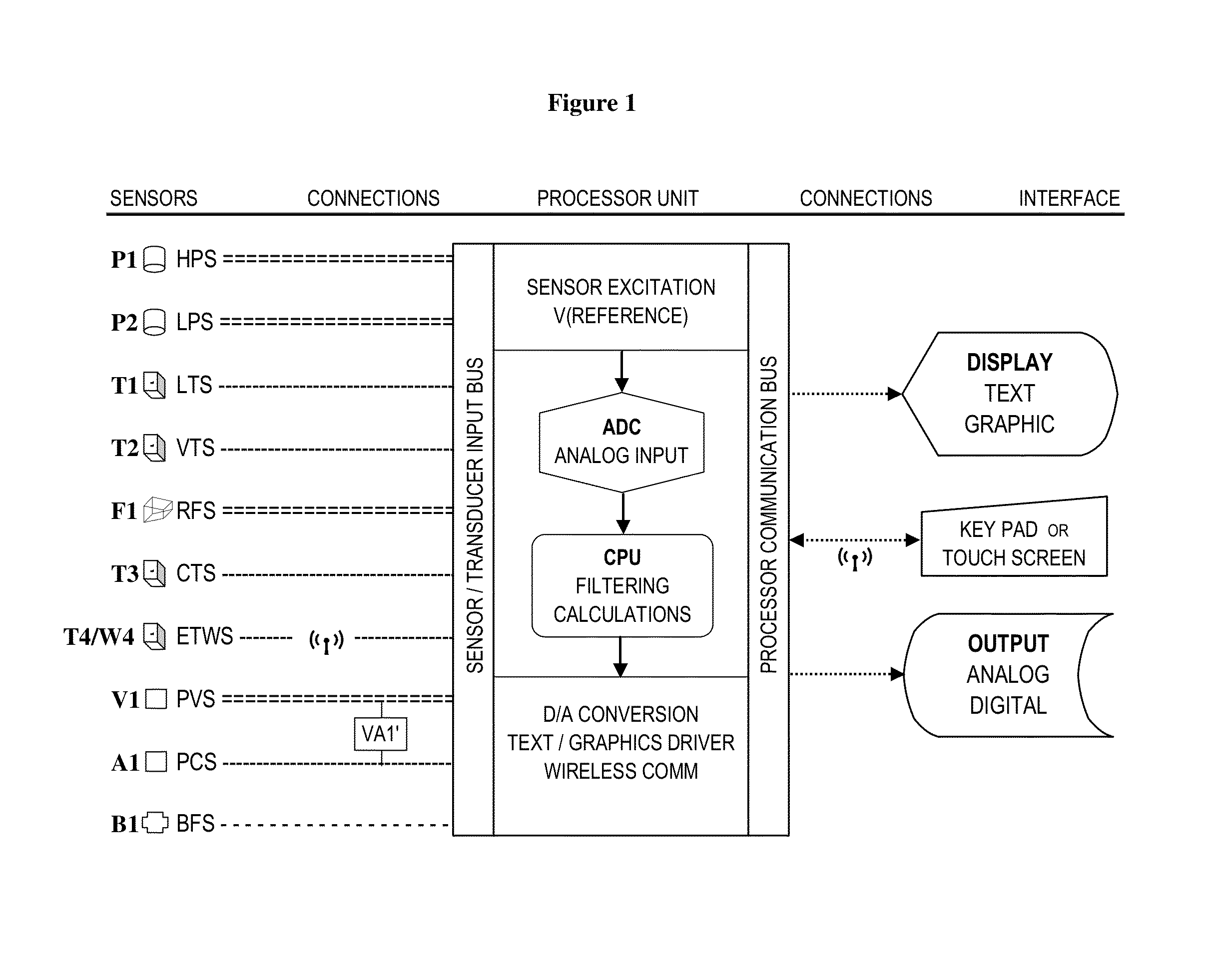
[0016]A block diagram of the preferred process for obtaining the output values and signals from the input sensors, and the signal pathways between the sensors, the processor unit, and the display and signal outputs and connections is shown in FIG. 1. Nine sensors and one optional sensor are arranged vertically along the processor input bus; their functions and connections are as follows. Note that T3, T4, and W4 can be optional if the user does not desire EER, IEER and COP output at ANSI / AHRI Standard 340 / 360 test conditions. Transducer T4W4 is the evaporator air inlet temperature and humidity sensor (ETWS). Signals from transducer T4W4 are hardwired to an analog input when attached to a packaged air-conditioner, refrigerator or heat pump, or via a 2.4 GHz IEEE 802.15.4 RF wireless transmission, or Bluetooth or other wireless transmission as would be known to one skilled in the art, to the processor unit input when the transducer must be remotely positioned some distance away in the...


PUM


Abstract

Measured efficiency of an air conditioner or heat pump system is needed to accurately evaluate the economics of operating the system to provide a known amount of cooling. Significant degradation of air-conditioner and or heat pump components increases the operating cost by lowering the capacity of the system and/or increasing the power consumption. The invention provides measurement of the energy efficiency of any operating DX cooling, refrigeration, or heating unit, expressed in standard units by measuring the cooling or heating capacity and the power usage.

Description

CROSS REFERENCE TO RELATED APPLICATIONS[0001]The present application claims the benefit under any relevant U.S. statute to U.S. Provisional Application No. 61 / 756,017 filed Jan. 24, 2013, titled EER METER AND OPTIMIZING FEEDBACK CONTROL FOR DX AIR-CONDITIONERS.FIELD OF THE INVENTION[0002]The present invention relates generally to heating, ventilation, air conditioning, and refrigeration (HVAC&R) equipment. It specifically addresses accurate measurement of the cooling and / or heating capacity, the power usage, the energy efficiency ratio and the coefficient of performance under actual operating conditions.BACKGROUND OF THE INVENTION[0003]The thermodynamic method used in nearly all air conditioners, refrigerators and heat pumps is the vapor compression cycle also called the refrigeration cycle. The cycle uses four primary components: a compressor, a condenser, an expansion device, and an evaporator; some systems may use additional components such as a receiver, additional heat exchange...

Claims


Application Information

Patent Timeline
Patent Type & Authority Patents(United States)
IPC IPC(8): G01R19/25F25B49/02
CPCG01R19/2513F25B49/02F25B2600/2513F25B2700/21151F25B2500/19F25B49/00F25B2700/1332F25B2700/15F25B2700/1931F25B2700/1933F25B2700/195F25B2700/21152F25B2700/21161F25B2700/21163F25B2700/21172F25B2500/18
Inventor WEST, MICHAEL, KENNETH
Owner ADVANTEK CONSULTING ENG
Why Eureka
Try Eureka