
Optimized de-inertia control method for kinetic hybrids

a kinetic hybrid and control method technology, applied in the direction of propulsion parts, instruments, transportation and packaging, etc., can solve the problems of low overall drive efficiency, low efficiency of flywheel control, and waste of close to half of energy, so as to optimize efficiency, optimize efficiency, and optimize the effect of vehicle efficiency without sacrificing performan

Active Publication Date: 2016-02-23
HE HONGPING +1
View PDF2 Cites 4 Cited by
  • Summary
  • Abstract
  • Description
  • Claims
  • Application Information

AI Technical Summary

Benefits of technology

[0011]If, however, there is a means to cancel the torque effect of the inertias at the vehicle driveshaft with a secondary power source (such as a flywheel), then the primary power source (an engine, a motor, or both) would only need to output enough torque to overcome rolling resistance, air drag, and internal losses, and could therefore be downsized considerably, resulting in lower cost, higher performance and higher efficiency.
[0014]The present invention provides a way to control a flywheel in a kinetic hybrid such that the torque of the flywheel on the vehicle driveshaft cancels out the passive torque effects of the vehicle's inertia due to changes in speed at the vehicle driveshaft in a significant and precise manner, reducing the power requirements of the primary power source and allowing for downsizing and its aforementioned benefits. In addition to providing a method to cancel the torque effects of the vehicle's inertia from the point of view of the primary power source, which is henceforth referred to as “de-inertia operation”, the present invention also provides a means to simultaneously operate the vehicle's primary power source on its ideal operation line, or IOL.
[0015]In one aspect, the present invention provides a method of determining a first rate of change of CVT ratio according to the flywheel speed, the current CVT ratio, power source inertia(s), the vehicle inertia, the flywheel inertia, and the vehicle acceleration desired. This first rate of change of CVT ratio controls de-inertia operation.
[0016]In another aspect, the present invention provides a method of determining a second rate of change of CVT ratio according to an IOL torque output of the primary power source, the current CVT ratio, power source inertia(s), the flywheel inertia, and the flywheel speed. This second rate of change of CVT ratio controls the power flow between the primary power source and the flywheel, maintaining the primary power source on its IOL to optimize efficiency whenever it is active.
[0017]In another aspect, the present invention provides for the integration of these two rates of change in the CVT ratio to comprise an optimized de-inertia CVT ratio control, which simultaneously achieves de-inertia operation and operates the kinetic hybrid vehicle's primary power source on its IOL to optimize the vehicle's efficiency without sacrificing its performance.

Problems solved by technology

In a city cycle, close to half of the energy is wasted due to inertia: a portion of the energy used is stored in the kinetic energy of the vehicle and is wasted during deceleration.
It is due to the passive effects of the vehicle's inertia on acceleration that vehicles must have an engine or motor that has high reserve power and consequently lower overall drive efficiency, operating below the ideal operation line (IOL).
In the prior art flywheel hybrids, cancelling the torque effect of inertia either was not an objective, or if it was, the flywheel control method was imprecise and was not able to significantly cancel out the effects of the vehicle inertia and power source inertia(s) on the vehicle's performance.

Method used


Image

  • Optimized de-inertia control method for kinetic hybrids
  • Optimized de-inertia control method for kinetic hybrids
  • Optimized de-inertia control method for kinetic hybrids

Examples


Embodiment Construction

[0021]The present invention is described herein with reference to the drawings. In the drawings, like reference numerals represent like elements.

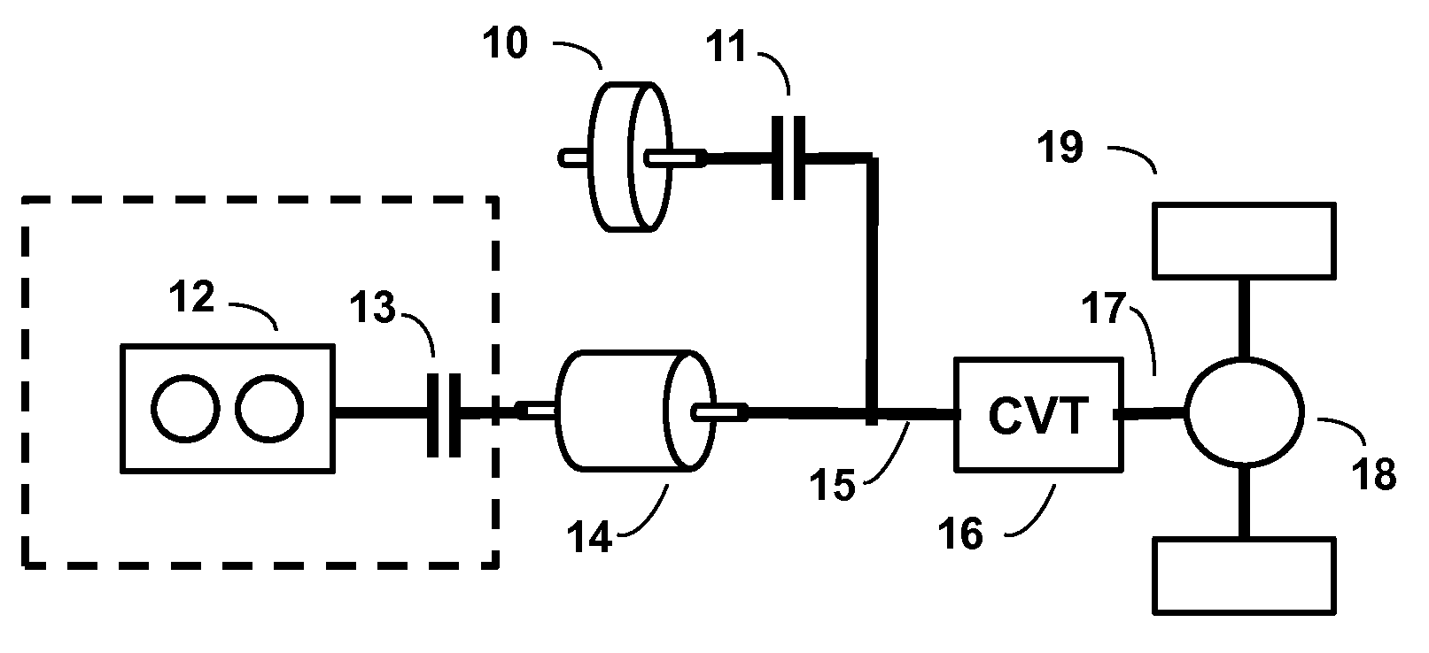
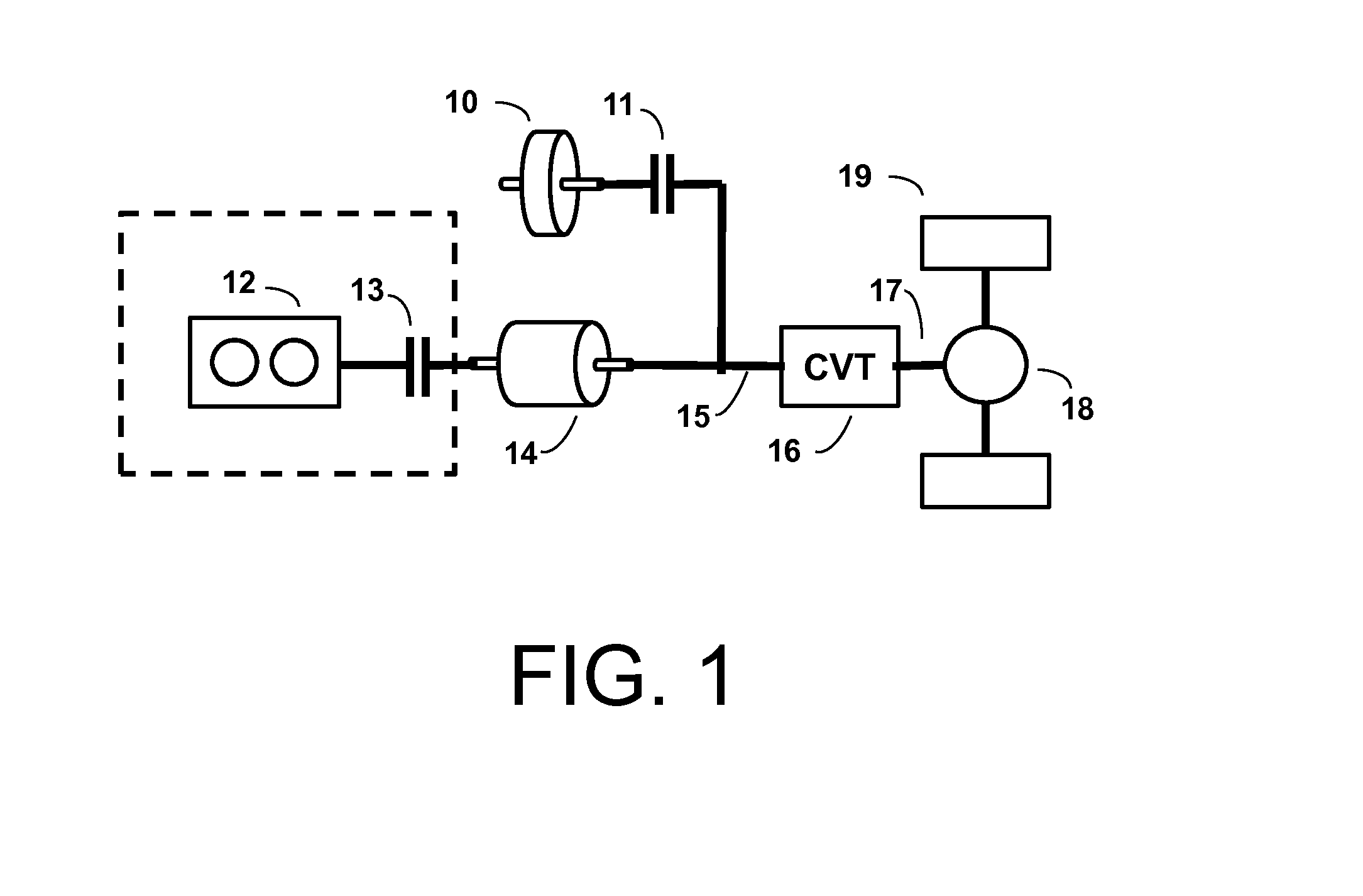
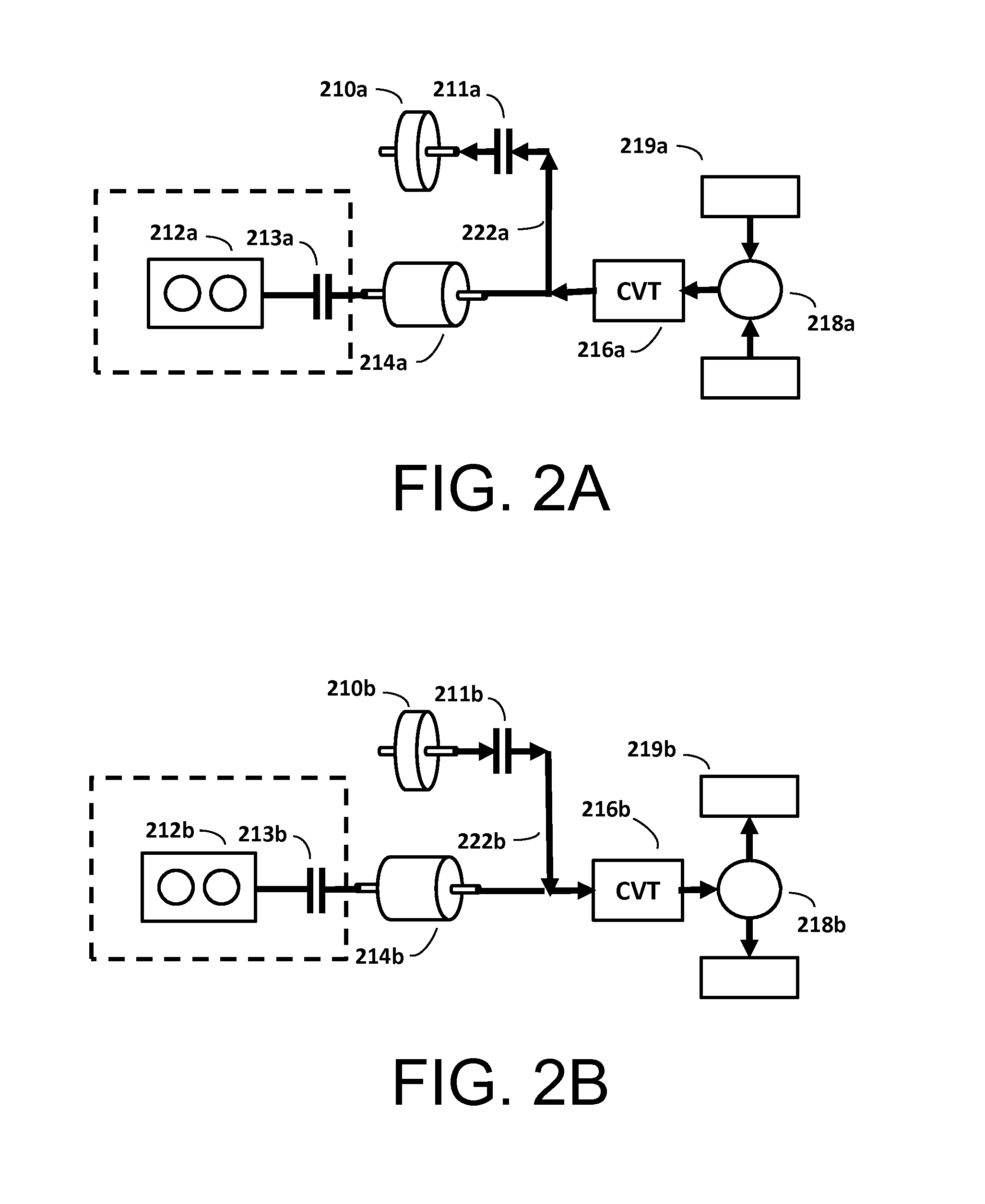
[0022]FIG. 1 represents a kinetic hybrid powertrain. The primary power source may be an internal combustion (IC) engine 12 or a traction motor / generator 14, or both may be present in a kinetic hybrid powertrain. In easily anticipated variations the engine 12 may be a turbine engine, or the primary power source may be considered to be some combination of one or more motors with at least one engine. If there is both an engine 12 and a motor 14 in the same powertrain, the motor 14 may be a through shaft motor and there may be an engine clutch 13 for coupling / decoupling the engine 12. The primary power source(s) is coupled to the input shaft 15 of a continuously variable transmission (CVT) 16, as is the flywheel 10 through the flywheel clutch 11, and the output shaft 17 of the CVT 16 is coupled to the final drive 18, which is connected to the v...


PUM


Abstract

Method for CVT and powertrain control in a kinetic hybrid that integrates two constituent control strategies at the same time, one for the kinetic energy exchange between a vehicle and a flywheel to recover the vehicle's kinetic energy and to cancel the effect of the vehicle's inertia on changes in speed, and one for operating the kinetic hybrid's prime mover on its ideal operation line to optimize efficiency. Two different rates of change in the CVT ratio are computed in real time and are superimposed to realize both strategies. Using the combined rate of change in the CVT ratio derived by the present invention to control the powertrain, the primary power source need not expend a significant portion of its power to overcome the vehicle's inertia, and performance is not compromised.

Description

CROSS REFERENCE TO RELATED APPLICATION(S)[0001]This application claims priority from U.S. Provisional Patent Application Ser. No. 61 / 843,634 filed Jul. 8, 2013 and 61 / 922,099, filed Dec. 31, 2013, which are incorporated by reference herein.BACKGROUND OF THE INVENTION[0002]1. Field of the Invention[0003]The present invention pertains in general to a method of controlling the CVT in a vehicle powertrain. More particularly, the invention relates to a method of control for a kinetic hybrid vehicle, where the prime mover is either a motor, an engine, or a combination of both, and a flywheel acts as both a secondary power source and a secondary energy storage.[0004]2. Description of the Related Art[0005]Transportation accounts for a significant portion of global energy use and pollution, and there have been considerable efforts worldwide to promote new technology in transportation to improve fuel efficiency, aimed at promoting energy independence and reducing greenhouse gas emissions. As ...

Claims


Application Information

Patent Timeline
Patent Type & Authority Patents(United States)
IPC IPC(8): B60L9/00B60L11/00B60W10/101B60W10/06B60W10/08G06F7/00G06F17/00G06F19/00G01G9/00B60K6/10
CPCB60W10/101B60W10/06B60W10/08B60K6/105B60W2510/10B60W2520/105B60W2710/10B60K6/30B60K6/48B60K6/543B60K2006/4825B60W2510/0695B60W2510/088B60W2510/1005B60W2540/10B60W2710/1005Y02T10/62
Inventor HE, HONGPINGHE, JING
Owner HE HONGPING
Learn More