Facing-targets-type sputtering apparatus

a sputtering apparatus and target type technology, applied in the direction of electrolysis components, vacuum evaporation coatings, coatings, etc., can solve the problems of high production costs, unsolved problems, and deterioration of vacuum seals with tim

Inactive Publication Date: 2005-04-19
FTS
View PDF17 Cites 17 Cited by
  • Summary
  • Abstract
  • Description
  • Claims
  • Application Information

AI Technical Summary

Benefits of technology

[0028]In the facing-targets-type sputtering apparatus according to the first aspect of the present invention, plasma is confined within the confinement space by means of the aforementioned magnetic fields, and thus sputtering is effectively performed. Conceivably, plasma confined by means of the facing-mode magnetic field dominates sputtering of the center portion of the target, whereas plasma confined by means of the magnetron-mode magnetic field dominates sputtering of the peripheral portion of the target. The present inventors have performed extensive studies on the magnetron-mode magnetic field which is required for regulating variation in film thickness in a width direction of the substrate and which can be locally regulated, and have found that, when a permanent magnet serving as magnetic-field regulation means for regulating the magnetron-mode magnetic field is appropriately provided on the back side of the target at a position on its centerline parallel to the substrate such that the permanent magnet faces toward the direction of the magnetron-mode magnetic field, variation in film thickness in a width direction of the substrate can be regulated. The present invention has been accomplished on the basis of this finding.
[0029]Conceivably, the magnetic-field regulation means locally regulates the magnetron-mode magnetic field extending to a position at which the regulation means is provided and to the vicinity of the position (i.e., the vicinity of the surface of the target), thereby partially regulating the plasma confinement effects exerted by the magnetron-mode magnetic field and the facing-mode magnetic field in the vicinity of the surface of the target. Therefore, sputtering rate in the vicinity of the surface of the target can be locally regulated, to thereby regulate variation in film thickness. No particular limitation is imposed on the magnetic-field regulation means, so long as the regulation means can regulate the magnetron-mode magnetic field, specifically in terms of the distribution pattern of magnetic fluxes and / or intensity of the magnetic field. Therefore, instead of the permanent magnet which provides great regulation effects, a magnetic material of high magnetic permeability which can regulate the magnetic resistance of a magnetron-mode magnetic circuit may be employed as the magnetic-field regulation means. Needless to say, the direction of the magnetic field of the permanent magnet may be the same as or opposite that of the magnetron-mode magnetic field.

Problems solved by technology

Thus, a large-sized apparatus is required, and utilization efficiency of a target is lowered, resulting in high production costs.
Since the sputtering apparatus has a structure in which a cooling jacket is provided at the interface between a support unit and a backing unit of the target, when the apparatus is operated for a long period of time, deterioration of a vacuum seal occurs with passage of time.
Therefore, such a problem has remained unsolved.

Method used


Image

  • Facing-targets-type sputtering apparatus
  • Facing-targets-type sputtering apparatus
  • Facing-targets-type sputtering apparatus

Examples


first embodiment

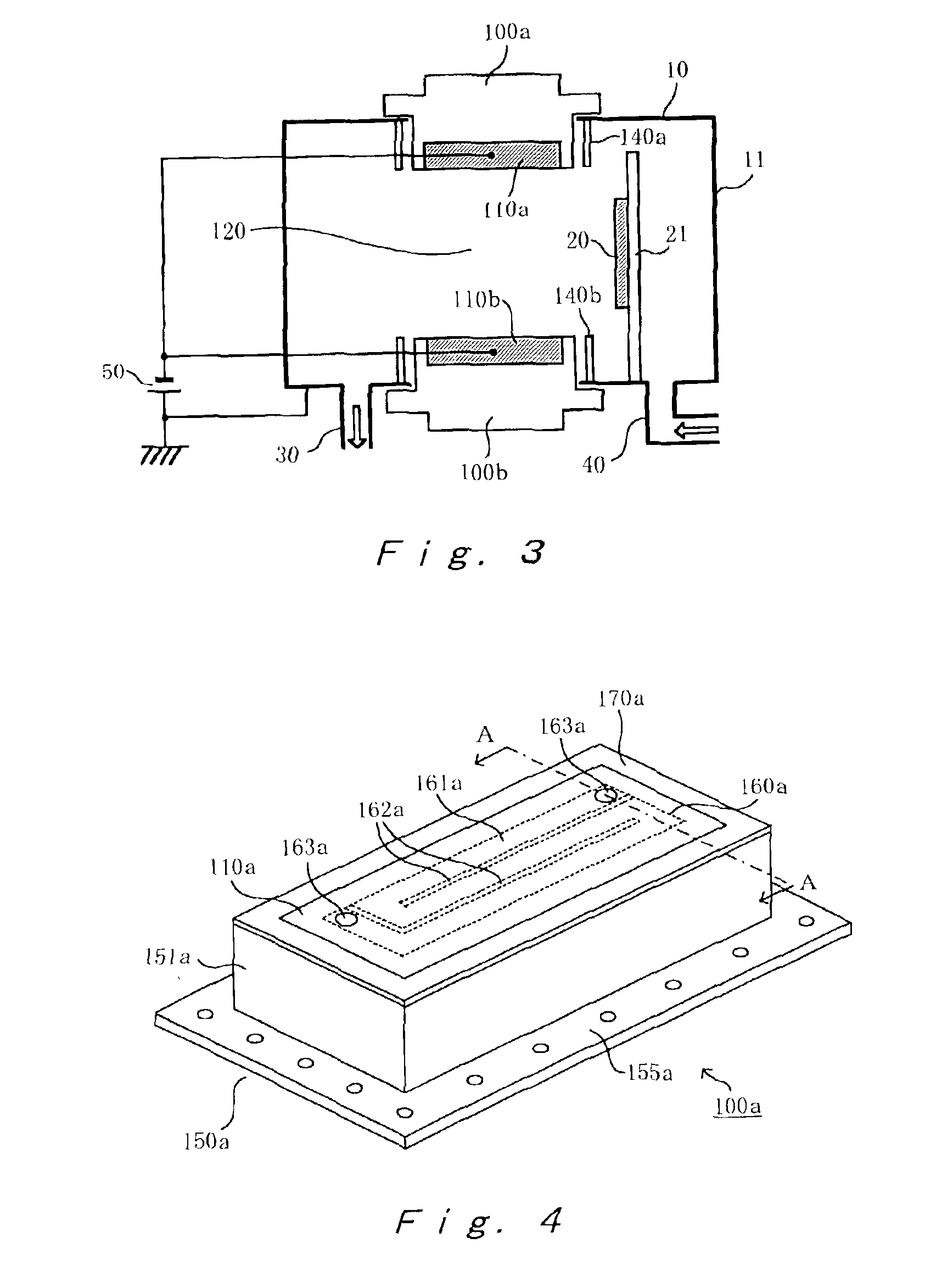
[0053]FIG. 3 is a schematic cross-sectional view showing a facing-targets-type sputtering apparatus according to a first embodiment of the present invention; FIG. 4 is a schematic perspective view showing a target unit employed in the sputtering apparatus shown in FIG. 3 according to the first embodiment of the present invention; FIG. 5 is a schematic vertical cross-sectional view of the target unit shown in FIG. 4, as taken along line A—A; and FIG. 6 is a schematic horizontal cross-sectional view of the target unit shown in FIG. 5, as taken along line B—B. The cross-section of a target unit 100a shown in FIG. 3 is shown in FIG. 5.

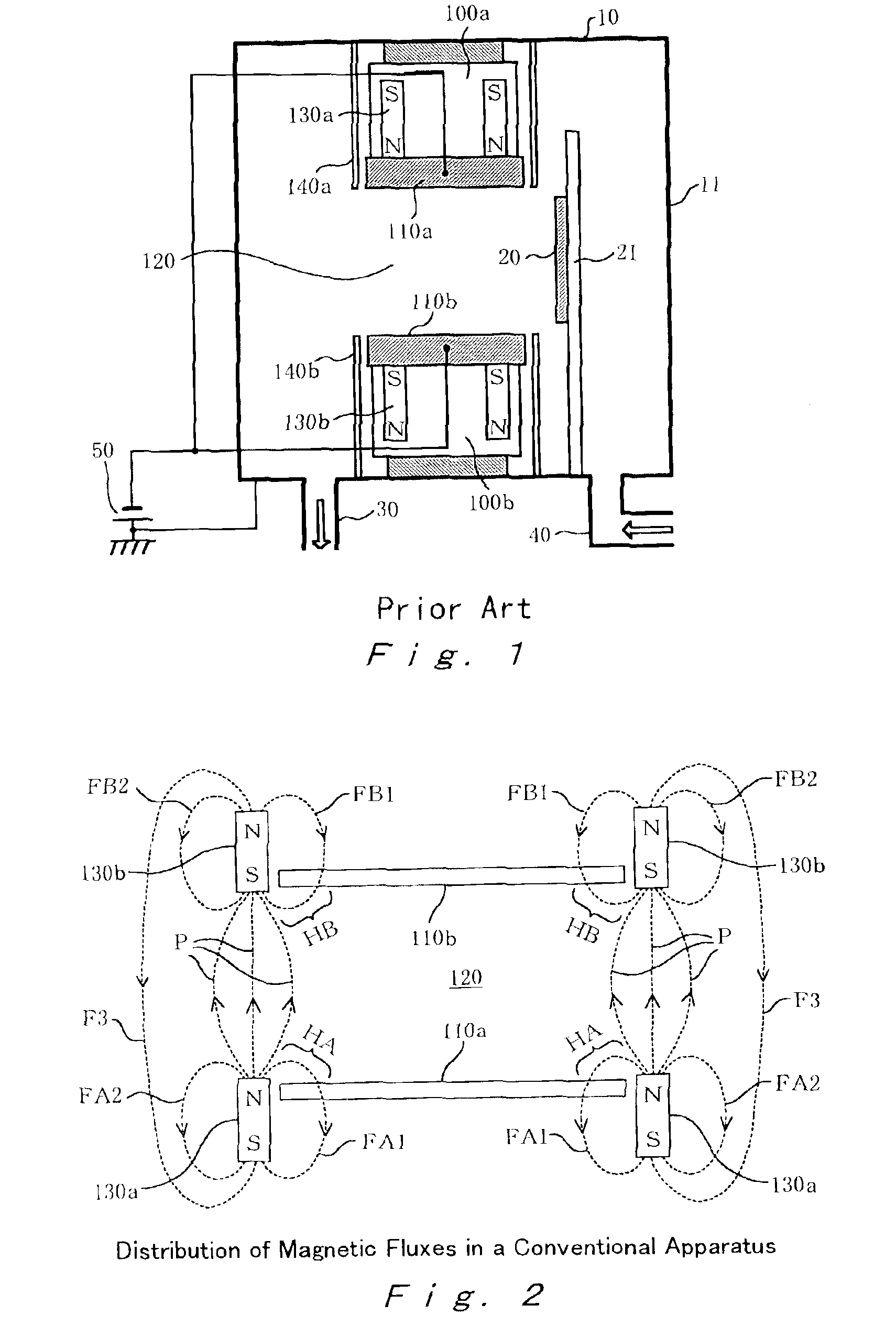
[0054]In FIG. 3, components corresponding to those in FIG. 1 are denoted by common reference numerals, and repeated description is omitted. The sputtering apparatus of the present embodiment differs from the conventional apparatus of FIG. 1 in the structure of target units 100a and 100b, and in that, in the sputtering apparatus of the present embodiment, o...

second embodiment

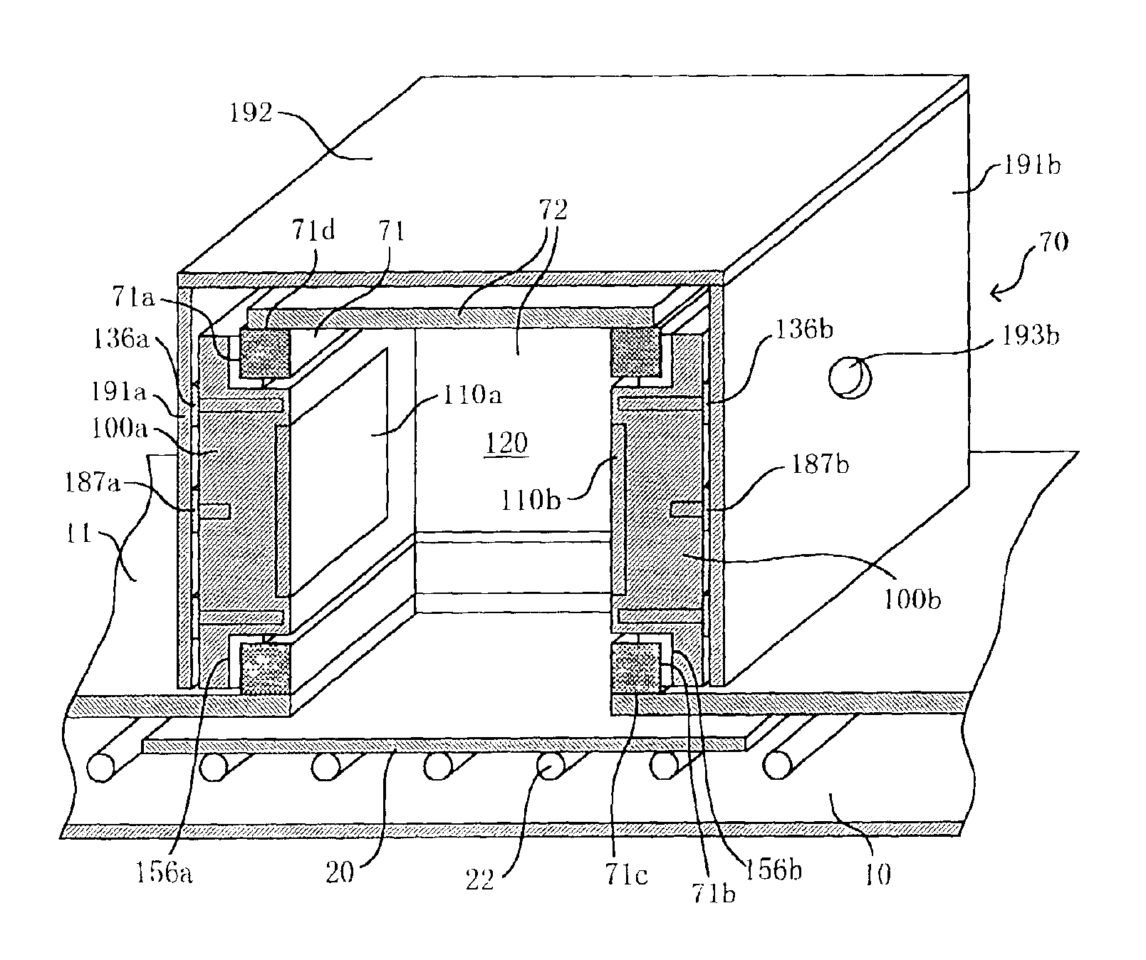
[0075]FIG. 7A is a schematic perspective view showing a facing-targets-type sputtering apparatus according to a second embodiment of the present invention; and FIG. 7B is a schematic cross-sectional view of the sputtering unit of the sputtering apparatus. Unlike the case where the target units 100a and 100b are mounted on the vacuum wall 11 of the vacuum chamber 10 as shown in FIG. 3, in the present embodiment, the target units 100a and 100b are mounted on opposing faces 71a and 71b of a rectangular parallelepiped frame 71, respectively, and faces 71d through 71f (a face 71e is not illustrated), excluding a face 71c which faces a substrate, are covered by use of closure plates, to thereby form a box-like unit 70. Since the facing-targets-type sputtering apparatus has a compact structure, maintenance of the apparatus is improved. In addition, the apparatus is suitable for mass-production at high productivity.

[0076]As shown in FIGS. 7A and 7B, the box-like unit 70 includes the rectang...

third embodiment

[0082]FIG. 8 is a schematic cross-sectional view showing the basic structure of a facing-targets-type sputtering apparatus according to a third embodiment of the present invention; and FIG. 9 is a schematic perspective view showing the sputtering apparatus according to the third embodiment including a box-like unit. Unlike the case where the target units 100a and 100b are mounted directly on the vacuum wall of the vacuum chamber, in the present embodiment, as in the case of the sputtering unit of the second embodiment, the target units 100a and 100b are hermetically mounted on opposing faces 71a and 71b (see FIG. 9) of a rectangular parallelepiped frame 71, respectively, and faces 71d through 71f (a face 71e located at the front side and a face 71f located at the back side are not illustrated), excluding a face 71c which faces a substrate, are hermetically covered by use of closure plates 72, to thereby form a box-like unit 70. The box-like unit 70 is mounted on the chamber wall 11 ...


PUM

PropertyMeasurementUnit
mesh sizeaaaaaaaaaa
thicknessaaaaaaaaaa
lengthaaaaaaaaaa

Abstract

Disclosed is a facing-targets-type sputtering apparatus including a sputtering unit including a pair of facing targets which are disposed a predetermined distance away from each other, and permanent magnets serving as magnetic-field generation means which are disposed around each of the facing targets, the permanent magnets being provided so as to generate a facing-mode magnetic field and a magnetron-mode magnetic field, the facing-mode magnetic field extending in the direction perpendicular to the facing targets in such a manner as to surround a confinement space provided between the targets, and the magnetron-mode magnetic field extending from the vicinity of a peripheral edge portion of each of the targets to a center portion thereof, thereby confining plasma within the confinement space by means of these magnetic fields for forming a thin film on a substrate disposed beside the confinement space, which apparatus further includes magnetic-field regulation means for regulating the magnetron-mode magnetic field. The magnetic-field regulation means is formed of, for example, a permanent magnet, and is provided on the back side of each of the targets.

Description

BACKGROUND OF THE INVENTION[0001]1. Field of the Invention[0002]The present invention relates to a facing-targets-type sputtering apparatus including a sputtering unit, in which a pair of facing targets are disposed a predetermined distance away from each other, and permanent magnets are disposed along the periphery of each facing target such that magnetic poles of one target face the corresponding magnetic poles of the other target. The sputtering apparatus is configured such that a magnetic field extending in the direction perpendicular to the facing targets is generated in such a manner as to surround a space provided between the facing targets (the space is hereinafter called a “confinement space”) so as to confine plasma within the confinement space and to perform sputtering of the targets, thereby forming a film on a substrate disposed beside the confinement space.[0003]2. Description of the Related Art[0004]A facing-targets-type sputtering apparatus is disclosed in Japanese P...

Claims


Application Information

Patent Timeline
Patent Type & Authority Patents(United States)
IPC IPC(8): C23C14/35H01J37/32H01J37/34C23C14/34
CPCH01J37/3405C23C14/352
Inventor KADOKURA, SADAOANPUKU, HISANAO
Owner FTS
Why Eureka
Try Eureka