

Light-emitting element
a technology of light-emitting elements and materials, which is applied in the field of light-emitting elements, can solve the problems of difficulty in making such a material which meets the two conditions at the same time, and achieves the effect of higher luminous efficiency
- Summary
- Abstract
- Description
- Claims
- Application Information
AI Technical Summary
Benefits of technology
Problems solved by technology
Method used
Image

Examples
embodiment 1
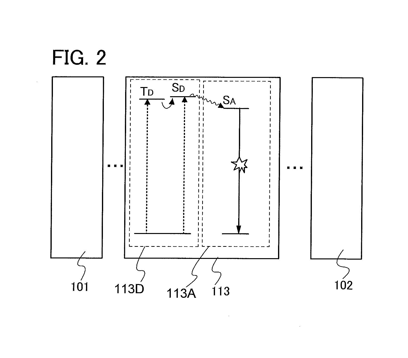
[0070]In a light-emitting element in which a thermally activated delayed fluorescent substance and a fluorescent material are mixed to be used, light emission occurs through the following energetic process.
[0071](1) where an electron and a hole are recombined in a fluorescent material, and the fluorescent material is excited (direct recombination process)
[0072](1-1) where the fluorescent material emits fluorescence when the excited state of the fluorescent material is a singlet excited state
[0073](1-2) where thermal deactivation occurs when the excited state of the fluorescent material is a triplet excited state
[0074]In the direct recombination process in (1), when the fluorescence quantum efficiency is high, high luminous efficiency can be obtained. The level of the singlet excited state of the thermally activated delayed fluorescent substance is preferably higher than the level of the singlet excited state of the fluorescent material.
[0075](2) where an electron and a hole are reco...
embodiment 2
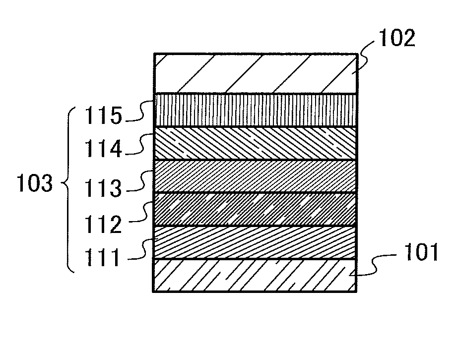
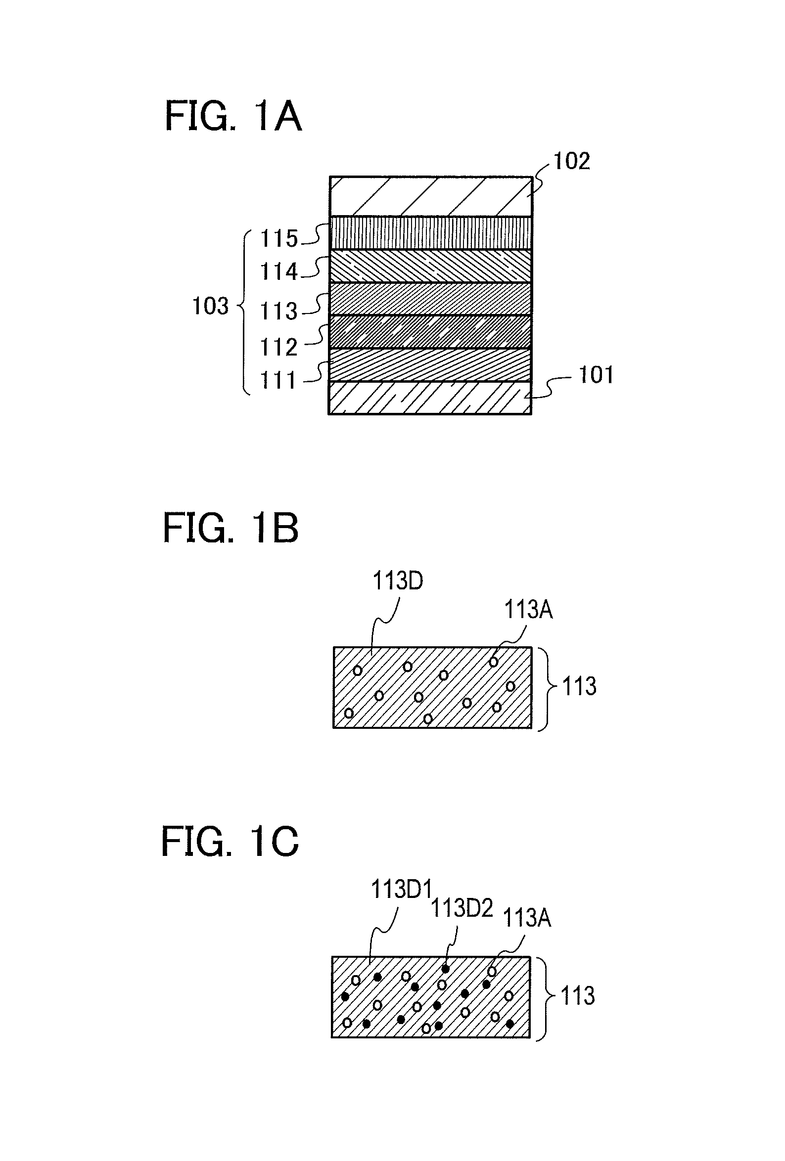
[0142]In this embodiment, a detailed example of the structure of the light-emitting element described in Embodiment 1 is described below with reference to FIGS. 1A to 1C.
[0143]A light-emitting element in this embodiment includes, between a pair of electrodes, an EL layer including a plurality of layers. In this embodiment, the light-emitting element includes the first electrode 101, the second electrode 102, and the EL layer 103 which is provided between the first electrode 101 and the second electrode 102. Note that the following description in this embodiment is made on the assumption that the first electrode 101 functions as an anode and that the second electrode 102 functions as a cathode. In other words, when a voltage is applied between the first electrode 101 and the second electrode 102 so that the potential of the first electrode 101 is higher than that of the second electrode 102, light emission can be obtained.
[0144]Since the first electrode 101 functions as the anode, th...
embodiment 3
[0172]In this embodiment, an example in which the light-emitting element described in Embodiment 1 or 2 is used for a lighting device is described with reference to FIGS. 3A and 3B. FIG. 3B is a top view of the lighting device, and FIG. 3A is a cross-sectional view taken along e-f in FIG. 3B.
[0173]In the lighting device in this embodiment, a first electrode 401 is formed over a substrate 400 which is a support and has a light-transmitting property. The first electrode 401 corresponds to the first electrode 101 in Embodiment 2.
[0174]An auxiliary electrode 402 is provided over the first electrode 401. Since this embodiment shows an example in which light emission is extracted through the first electrode 401 side, the first electrode 401 is formed using a material having a light-transmitting property. The auxiliary electrode 402 is provided in order to compensate for the low conductivity of the material having a light-transmitting property, and has a function of suppressing luminance u...
PUM
 Abstract
Description
Claims
Application Information