
Optimal trajectory control for LLC resonant converter for LED PWM dimming

a resonant converter and trajectory control technology, applied in the direction of electric variable regulation, process and machine control, instruments, etc., can solve the problems of reducing efficiency, low efficiency, and high cost, and achieve the effect of not being significantly susceptible to transients and high uniformity of light output flux

Active Publication Date: 2016-03-01
VIRGINIA TECH INTPROP INC
View PDF11 Cites 10 Cited by
  • Summary
  • Abstract
  • Description
  • Claims
  • Application Information

AI Technical Summary

Benefits of technology

[0007]It is therefore an object of the present invention to provide a unitary, resonant power supply capable of providing high uniformity of light output flux of LEDs in an array and which is not significantly susceptible to transients caused by use of PWM for dimming.
[0008]It is another object of the invention to provide a switching pattern control that substantially avoids transient effects in a resonant power converter and thus permits use of PWM for dimming consistent with use of a resonant power converter.
[0009]It is a further object of the invention to maintain efficiency of a resonant power converter providing power to an LED array over a full range of dimming ratio.

Problems solved by technology

However, dimming of LEDs presents some problems in the design of power supplies for LED arrays particularly in providing good uniformity of light output of all LEDs in an array and avoiding perceptible flickering consistent with high efficiency of the power supply.
For example, driving LEDs individually or in long, series connected strings with individual discrete power supplies is cost prohibitive and generally would require complex cross-regulation to achieve acceptable uniformity of light flux.
Also, since power supplies are designed for highest efficiency at a particular voltage and frequency, efficiency is often greatly reduced as voltage is controlled, particularly when that voltage control is achieved by frequency control in resonant power converters.
Moreover, Also, since light output flux of LEDs terminates immediately upon interruption of current, duty cycle or pulse width modulation (PWM) must be performed at a switching cycle frequency above about 85 Hz whereas such a problem is not presented by incandescent bulbs which exhibit a decrease in light output flux over the period of filament cooling.
However, while steady-state performance of resonant power converters is well-matched to power requirements of LEDs other than loss of efficiency due if switching frequency is used to control voltage, interruption of input or output of power as is necessary for PWM or duty cycle modulation (e.g. for dimming) causes transients in the resonant circuit that may have perceptible adverse effects on light output flux.

Method used


Image

  • Optimal trajectory control for LLC resonant converter for LED PWM dimming
  • Optimal trajectory control for LLC resonant converter for LED PWM dimming
  • Optimal trajectory control for LLC resonant converter for LED PWM dimming

Examples


Embodiment Construction

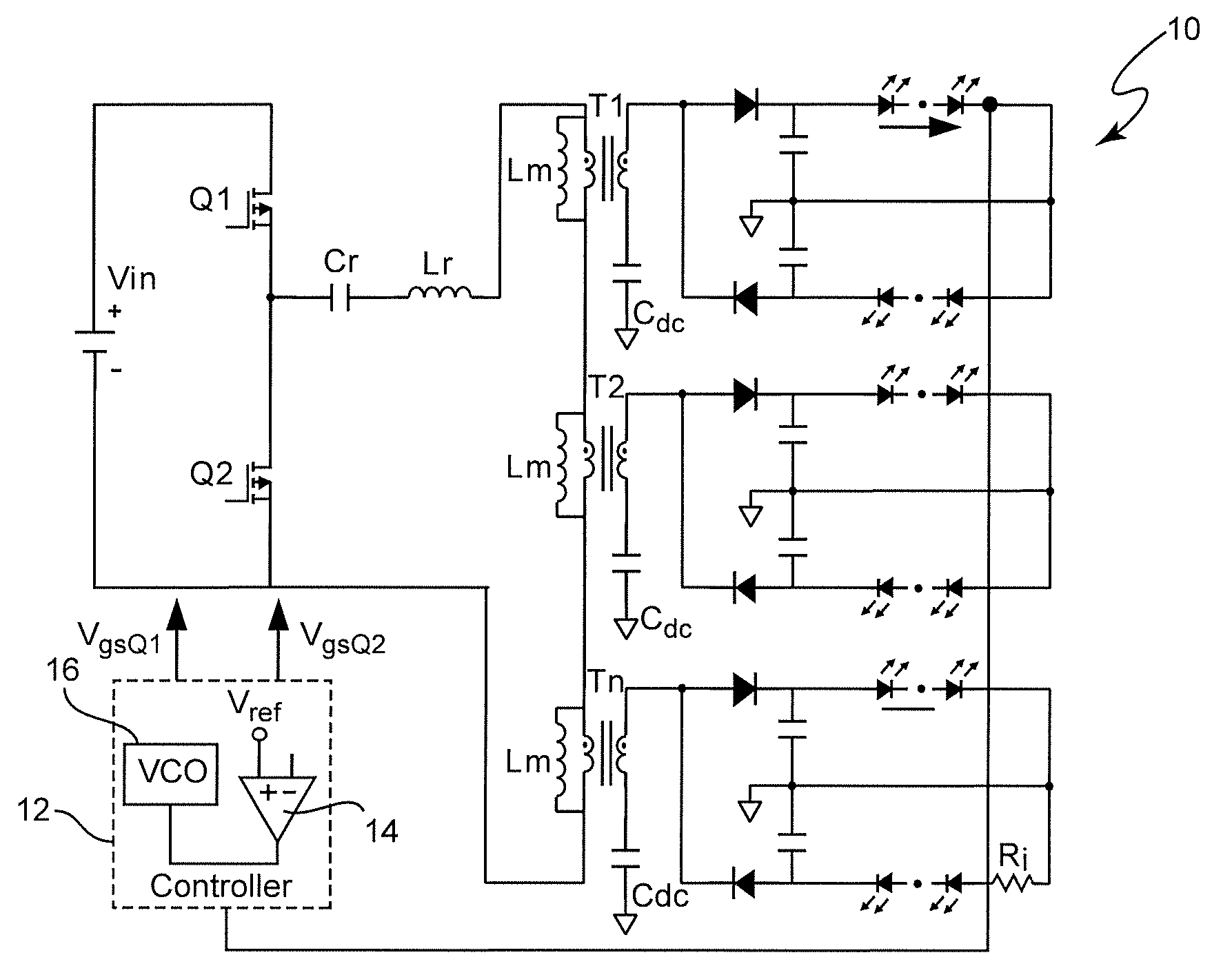
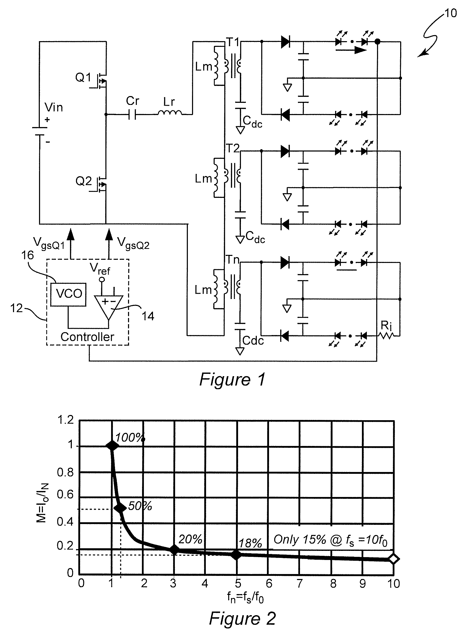
[0030]Referring now to the drawings, and more particularly to FIG. 1, there is shown a schematic diagram of an exemplary resonant single stage multi-channel constant current (MC3) power converter 10 useful for conveying an understanding the problems addressed by the invention. Since this power supply arrangement is somewhat similar in some aspects to some of the power supply arrangements disclosed in U.S. patent application Ser. No. 13 / 114,181, filed May 24, 2011, and a continuation-in-part thereof, U.S. patent application Ser. No. 13 / 930,200, filed Jun. 28, 2013, both of which are hereby fully incorporated by reference, no portion of FIG. 1 is admitted to be prior art in regard to the present invention. Specifically, while the power converter of FIG. 1 includes features of driving pairs of LED strings (a pair of LED strings constituting two channels) using voltage doubler circuits, series connection of transformer primary windings to ensure equal currents to all voltage doublers an...


PUM


Abstract

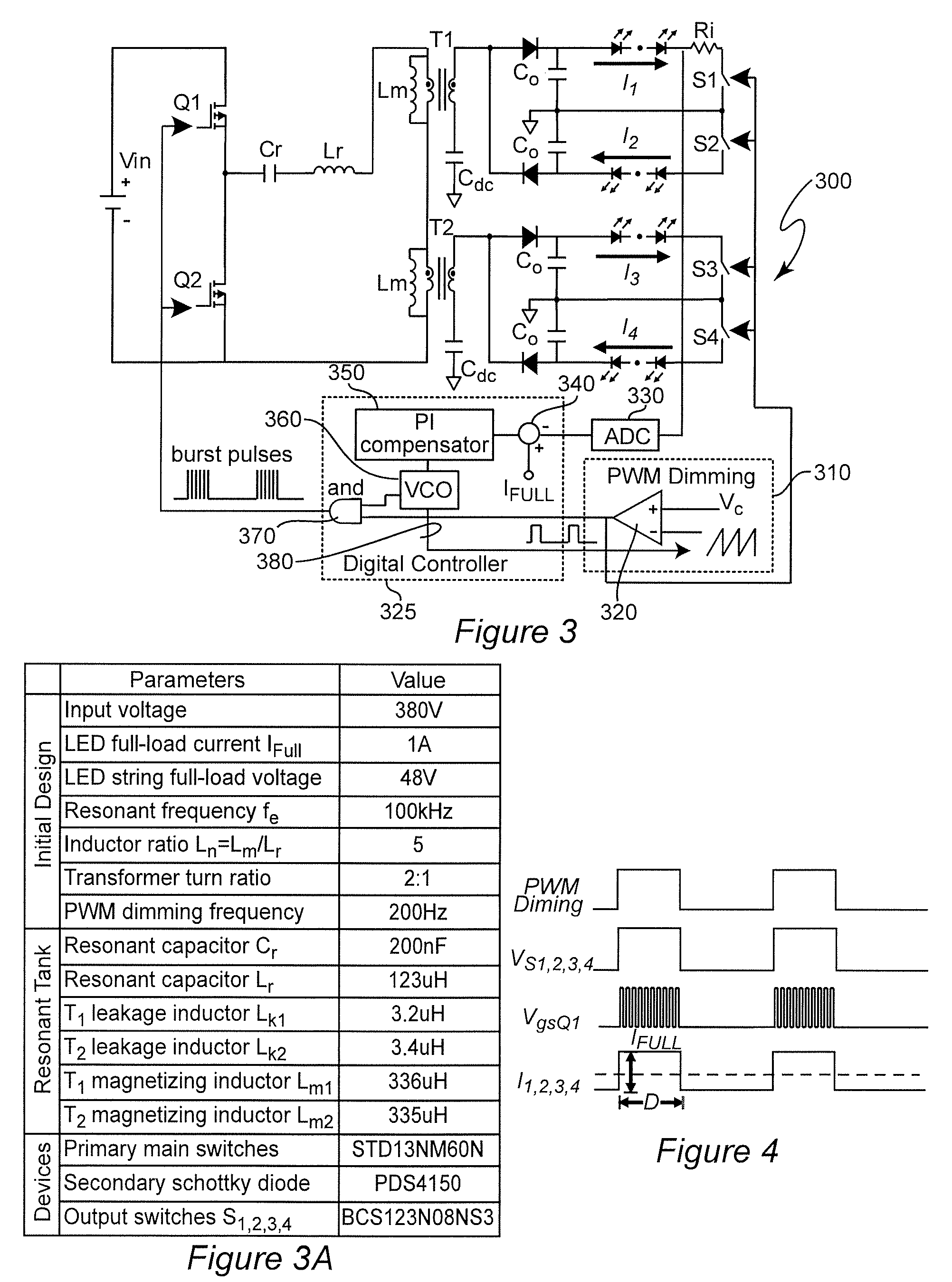
Pulse width modulation is provided for controlling a resonant power converter, particularly for dimming of light emitting diode arrays without loss of efficiency. Dynamic oscillation due to the beginning of a pulse width modulated pulse burst is limited by shortening of the first and / or last pulse of a pulse bust such that the first pulse of a subsequent pulse burst close to or to connect with a full load steady-state voltage / current trajectory of the power converter. Pulse shortening made be made substantially exact to virtually eliminate dynamic oscillation but substantial reduction in dynamic oscillation is provided if inexact or even performed randomly.

Description

CROSS-REFERENCE TO RELATED APPLICATIONS[0001]This application claims benefit of priority of U.S. Provisional Application 61 / 814,943, filed Apr. 23, 2013, which is hereby incorporated by reference in its entirety.FIELD OF THE INVENTION[0002]The present invention generally relates to Illumination arrangements using light-emitting diodes (LEDs) and, more particularly, to operation of resonant power converters for providing power to such illumination arrangements.BACKGROUND OF THE INVENTION[0003]Light-emitting diodes (LEDs) have been known for use in indicators and selective electronic displays for many years. Many recent advances in the technology of light-emitting diodes (LEDs) has caused increased interest in using LEDs for purposes of illumination and, indeed, made LED arrays the illumination medium of choice for numerous applications such as exterior and interior area illumination and backlighting of display panels due to the efficiency, spectral content, long lifetime, eco-friendl...

Claims


Application Information

Patent Timeline
Patent Type & Authority Patents(United States)
IPC IPC(8): H05B37/00H05B39/00H05B41/00H02M3/335H05B33/08H02M1/00H02M3/337H05B44/00
CPCH02M3/33507H05B33/0815H02M3/337H02M3/33561H02M2001/0058Y02B70/1433Y02B70/1491H05B45/46H05B45/39H05B45/327Y02B70/10H05B45/3725H02M1/0058H02M3/01H02M3/33571
Inventor FENG, WEIYILEE, FRED, C.JI, SHU
Owner VIRGINIA TECH INTPROP INC
Learn More