Single ended sensing circuits for signal lines

a sensing circuit and signal line technology, applied in the field of single-ended sensing circuits, can solve problems such as performance degradation, and achieve the effects of fast and accurate sensing of the first node, fast pre-charge of the second node, and fast ra

Active Publication Date: 2016-03-08
MARVELL ASIA PTE LTD
View PDF14 Cites 8 Cited by
  • Summary
  • Abstract
  • Description
  • Claims
  • Application Information

AI Technical Summary

Benefits of technology

[0010]It should be noted that, during this pre-charging mode, the isolation field effect transistor will initially be turned on because the voltage on the gate (Vg) of the isolation field effect transistor minus the voltage on the source (VS) of the isolation field effect transistor (which is initially reset to zero) (i.e., Vgs) will be greater than the first threshold voltage of that isolation field effect transistor. Thus, the first node and second node will pre-charge at the same relatively fast rate. However, when the voltage on the second node reaches a value that results in Vgs being equal to or below the first threshold voltage, the isolation field effect transistor will turn off. When the isolation field effect transistor turns off, the first node will continue pre-charging to first pre-charged voltage (e.g., Vdd) at an even faster rate because the first and second nodes are isolated from each other. As mentioned above, once the first node is pre-charged to the first pre-charge voltage, the output of the sense amplifier will switch to a LOW output signal. This LOW output signal can cause the second pre-charge device to automatically turn off (i.e., to cause the second pre-charge device to stop pre-charging the second node). Thus, a second pre-charge device on the second node can be used so that a relatively fast pre-charge of the second node can be achieved and, particularly, so that the second node can be pre-charged to the desired second pre-charge voltage within a desired amount of time.
[0011]During a sensing mode, the reference voltage generator can similarly apply the reference voltage to the gate of the isolation field effect transistor. Again, if no voltage decrease is sensed at the first node, the output signal at the output of the sense amplifier will remain a LOW output signal. However, upon sensing a voltage decrease at the first node, the sense amplifier can switch the LOW output signal to a HIGH output signal. It should be noted that the reference voltage can be pre-selected so that a relatively fast and accurate sensing of the first node can be achieved. For example, the reference voltage can be pre-selected such that the second threshold voltage of the sense amplifier is greater than the reference voltage minus the first threshold voltage of the isolation field effect transistor. Thus, a voltage decrease at the first node to an actual voltage that is below the second threshold voltage of the sense amplifier will occur relatively quickly following a corresponding voltage decrease at the second node, thereby causing the sense amplifier to switch the output signal at the output from the LOW output signal to a HIGH output signal within a desired amount of time.
[0012]Also disclosed herein is another sensing circuit that combines the features of the two different sensing circuits described above. Specifically, this sensing circuit can comprise at least a first node (i.e., a sense node), a second node (i.e., a signal line node), an isolation field effect transistor having a first threshold voltage, a variable reference voltage generator, a first pre-charge device, a second pre-charge device and a sense amplifier having a second threshold voltage. The second node can be electrically connected to a signal line. The isolation field effect transistor can comprise a source, which is also electrically connected to the second node, a drain, which is electrically connected to the first node, and a gate, which is electrically connected to the variable reference voltage generator. The first pre-charge device can be electrically connected to the first node. The second pre-charge device can be electrically connected to the second node. Finally, the sense amplifier can comprise an input, which receives an input signal from the first node, and an output, which outputs an output signal and is further electrically connected to the second pre-charge device.
[0013]During a pre-charging mode, the variable reference voltage generator can apply a first reference voltage to the gate of the isolation field effect transistor and the first and second pre-charge devices can be turned on (e.g., by a global pre-charge enable signal). As a result, the first node can be pre-charged to a first pre-charge voltage (e.g., Vdd), the second node can be pre-charged to a second pre-charge voltage that is lower than the first pre-charge voltage, the input signal from the first node to the input of the sense amplifier can become a HIGH input signal and the output signal at the output of the sense amplifier can become a LOW output signal.
[0014]It should be noted that, during this pre-charging mode, the isolation field effect transistor will initially be turned on because the voltage on the gate (Vg) of the isolation field effect transistor minus the voltage on the source (VS) of the isolation field effect transistor (which is initially reset to zero) (i.e., Vgs) will be greater than the first threshold voltage of that isolation field effect transistor. Thus, the first node and second node will initially pre-charge at the same relatively fast rate. However, when the voltage on the source reaches a value that results in Vgs being equal to or below the first threshold voltage, the isolation field effect transistor will turn off. When the isolation field effect transistor turns off, the first node will continue pre-charging to the first pre-charged voltage (e.g., Vdd) at an even faster rate because the first and second nodes are isolated from each other. As mentioned above, once the first node is pre-charged to the first pre-charge voltage, the output of the sense amplifier will switch to a LOW output signal. This LOW output signal can cause the second pre-charge device to automatically turn off (i.e., can cause the second pre-charge device to stop pre-charging the second node). Additionally, the rate at which the second node is pre-charged will decrease as the actual voltage on the second node approaches an amount equal to the first reference voltage minus the first threshold voltage of the isolation field effect transistor. Consequently, the higher first reference voltage, the faster the desired second pre-charge voltage can be reached. Thus, a combination of a relatively high first reference voltage and a second pre-charge device on the second node can be used so that a relatively fast pre-charge of the second node can be achieved and, particularly, so that the second node can be pre-charged to the desired second pre-charge voltage within a desired amount of time.
[0015]During a sensing mode, the variable reference voltage generator can apply a second reference voltage that is less than the first reference voltage to the gate of the isolation field effect transistor. Again, if no voltage decrease is sensed at the first node, the output signal at the output of the sense amplifier will remain a LOW output signal. However, upon sensing a voltage decrease at the first node, the sense amplifier can switch the LOW output signal to a HIGH output signal. It should be noted that the second reference voltage can be pre-selected so that a relatively fast and accurate sensing of the first node can be achieved. For example, the second reference voltage can be pre-selected such that, as mentioned above, it is less than the first reference voltage and further such that the second threshold voltage of the sense amplifier is greater than the second reference voltage minus the first threshold voltage of the isolation field effect transistor. Thus, a voltage decrease at the first node to an actual voltage that is below the second threshold voltage of the sense amplifier will occur relatively quickly following a corresponding voltage decrease at the second node, thereby causing the sense amplifier to switch the output signal at the output from the LOW output signal to a HIGH output signal within a desired amount of time.

Problems solved by technology

To compensate for these variations, sensing circuits typically operate with pessimistic timing margins, which degrade performance.

Method used


Image

  • Single ended sensing circuits for signal lines
  • Single ended sensing circuits for signal lines
  • Single ended sensing circuits for signal lines

Examples


Embodiment Construction

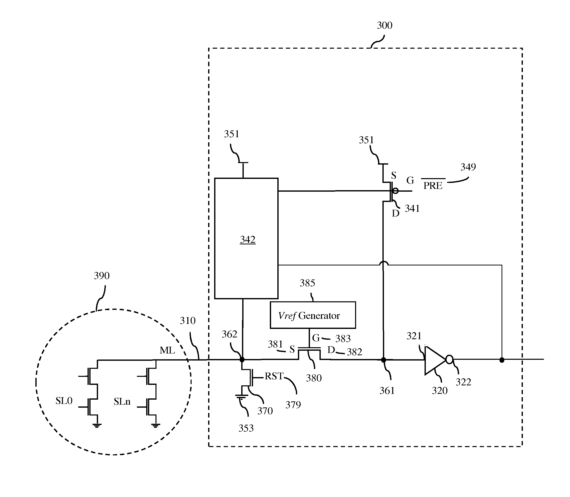
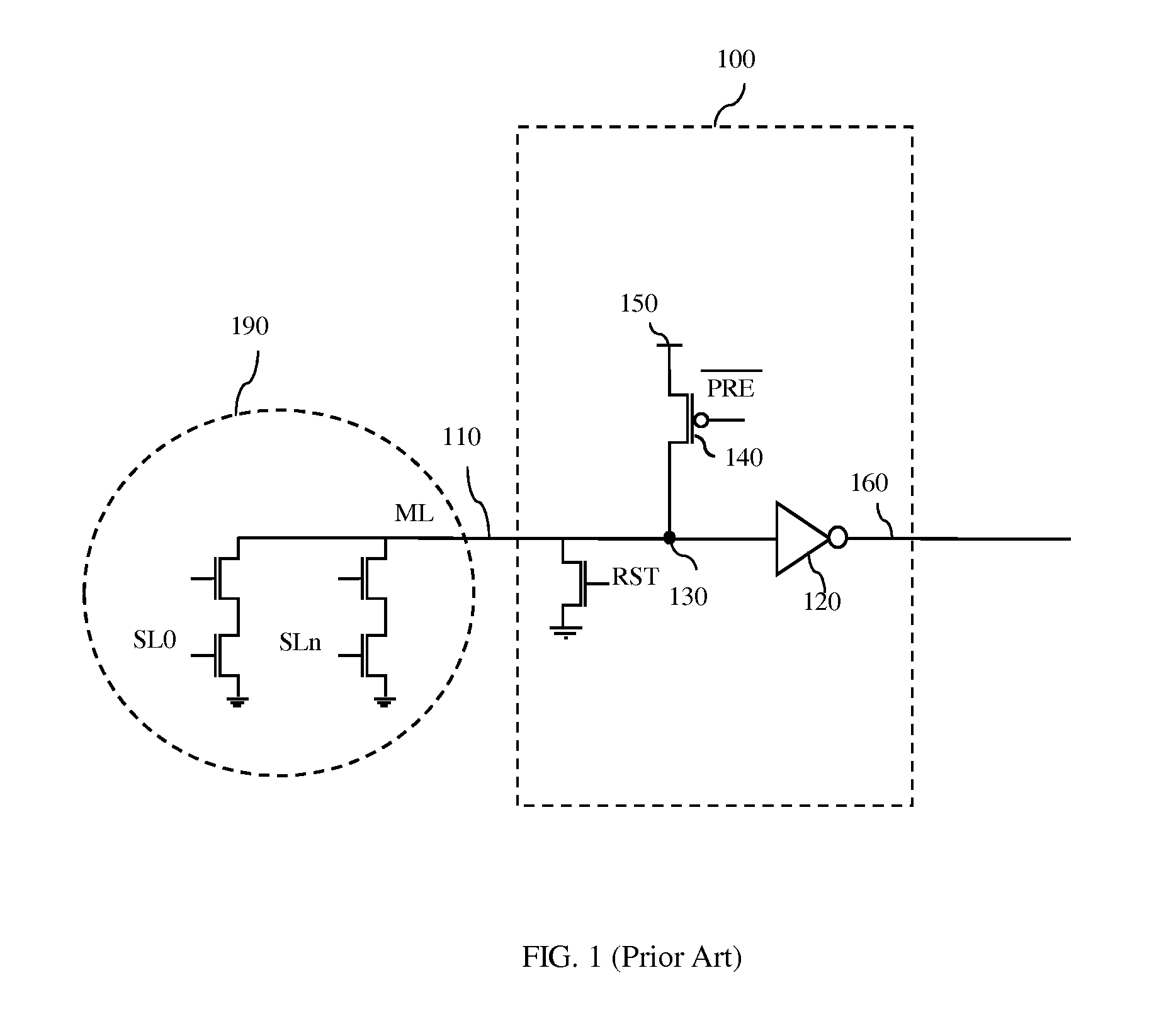
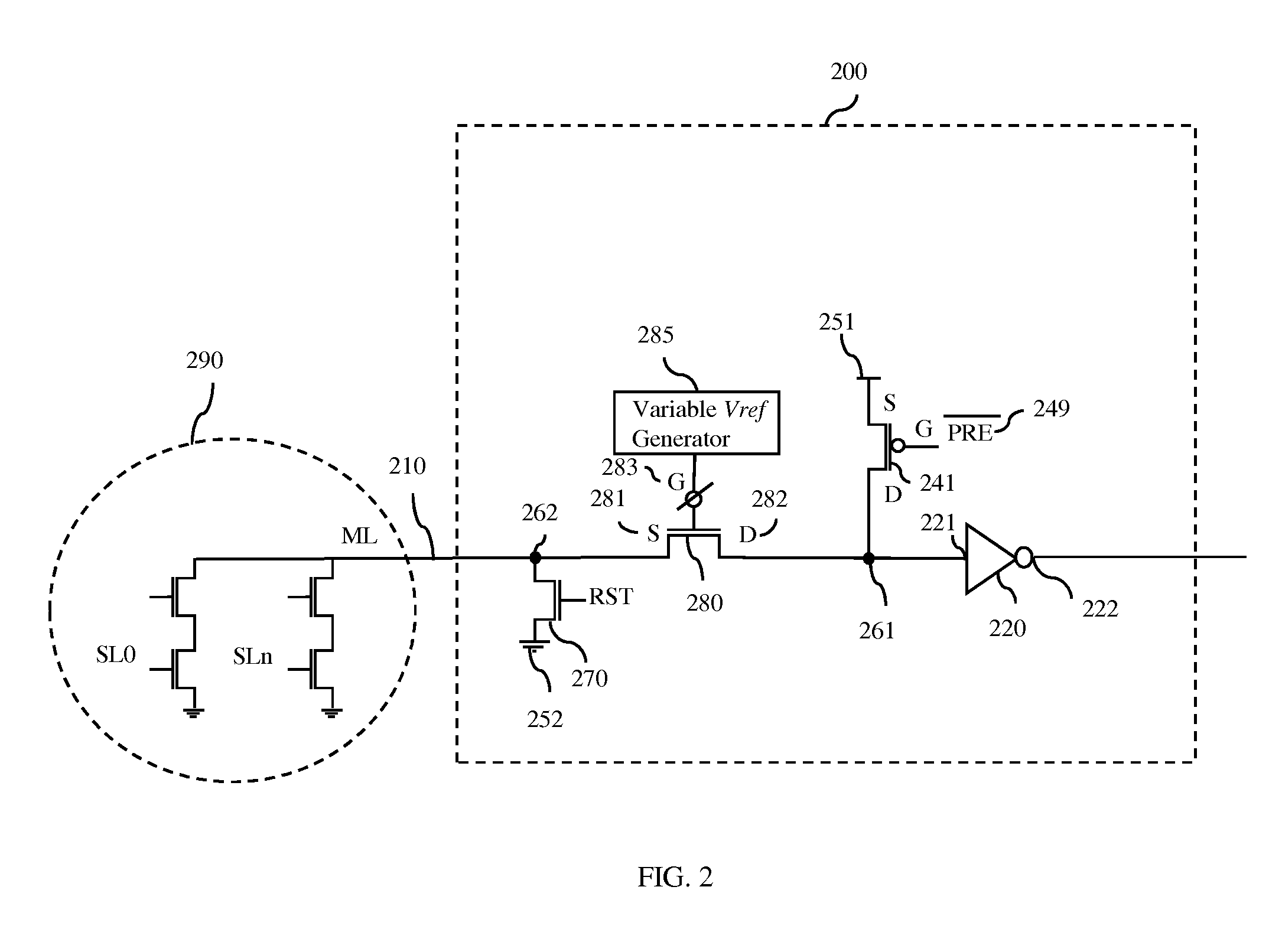
[0029]As mentioned above, memory circuits, such as content addressable memory (CAM) circuits, dynamic random access memory (DRAM) circuits, static random access memory (SRAM) circuits, etc., often incorporate single-ended sensing circuits to sense the value of a signal and, particularly, a small signal on a signal line (e.g., a match line in the case of a CAM circuit, a bit line in the case of a DRAM circuit, a bit line in the case of an SRAM circuit, etc.). Those skilled in the art will recognize that the term “single-ended” refers to the fact that the sensing circuits sense the value of a signal on a single signal line input into a sense amplifier as opposed to comparing the values of signals on two separate signal lines input into a sense amplifier. Recently, technology scaling (e.g., to sub-100 nm dimensions) has resulted in relatively large random variations in manufactured semiconductor devices incorporated into such memory circuits and, particularly, has resulted in relativel...


PUM


Abstract

Disclosed are single-ended sensing circuits. Each of the sensing circuits comprises at least a sense amplifier connected to a sense node, an isolation field effect transistor (FET) connected in series between the sense node and a signal line node, and a pre-charged device connected to the sense node. In order to achieve a relatively fast pre-charge of both the sense and signal line nodes and to also achieve a relatively fast and accurate sense of the sense node, the single-ended circuits further incorporate a variable reference voltage generator connected to the gate of the isolation FET for selectively applying different reference voltages to the gate during pre-charging and sensing operations, respectively, and/or a second pre-charge device connected to the signal line node for facilitating pre-charging of that signal line node.

Description

BACKGROUND[0001]The present disclosure relates to signal line sensing and, more particularly, to single-ended sensing circuits configured for relatively fast pre-charging operations and relatively fast and accurate sensing operations.[0002]Memory circuits, such as content addressable memory (CAM) circuits, dynamic random access memory (DRAM) circuits, static random access memory (SRAM) circuits, etc., often incorporate single-ended sensing circuits to sense the value of a signal and, particularly, a small signal on a signal line (e.g., a match line in the case of a CAM circuit, a bit line in the case of a DRAM circuit, a bit line in the case of an SRAM circuit, etc.). Those skilled in the art will recognize that the term “single-ended” refers to the fact that the sensing circuits sense the value of a signal on a single signal line input into a sense amplifier as opposed to comparing the values of signals on two separate signal lines input into a sense amplifier. Recently, technology...

Claims


Application Information

Patent Timeline
Patent Type & Authority Patents(United States)
IPC IPC(8): G11C7/08G11C7/06G11C7/12G11C15/04
CPCG11C7/08G11C7/067G11C7/12G11C15/04G11C2207/002
Inventor ARSOVSKI, IGORHEBIG, TRAVIS R.
Owner MARVELL ASIA PTE LTD
Why Eureka
Try Eureka