Inductive power transfer using a relay coil

a relay coil and power transfer technology, applied in the field of inductive power transfer, can solve the problems of reducing the efficiency of conventional 2-coil systems, and reducing the so as to improve the overall system energy efficiency, reduce current stress and component current ratings, and increase transmission distances

Active Publication Date: 2016-03-08
CONVENIENTPOWER HK
View PDF5 Cites 4 Cited by
  • Summary
  • Abstract
  • Description
  • Claims
  • Application Information

AI Technical Summary

Benefits of technology

[0009]Compared to conventional designs without an intermediate relay coil, designs of this type can have larger transmission distances between the charging system and the charged device, higher overall system energy efficiency and / or lower current stress and component current ratings. For example, designs of this type can support transmission distances of greater than 3 cm.

Problems solved by technology

However, in the Qi standard version 1.1, the distance or gap between the surface of a wireless charging pad (or literally the transmitter coil) and the receiver coil of the load is typically limited to 5 mm.
For wireless power transfer with an extended transmission distance, the conventional 2-coil system (i.e., one transmitter coil and one receiver coil separated by the transmission gap) loses efficiency quickly as the gap increases.
However, it has been mathematically proven that, although the maximum power transfer principle can extend the transmission distance, it does so at the expense of energy efficiency.
Any wireless power system based on impedance matching or the maximum power transfer theorem cannot achieve energy efficiency higher than 50%.
However, as previously mentioned, even if the maximum energy efficiency approach is adopted in a conventional 2-coil system, the energy efficiency will drop exponentially with transmission distance.
However, there is an incomplete understanding of these types of systems.

Method used


Image

  • Inductive power transfer using a relay coil
  • Inductive power transfer using a relay coil
  • Inductive power transfer using a relay coil

Examples


examples

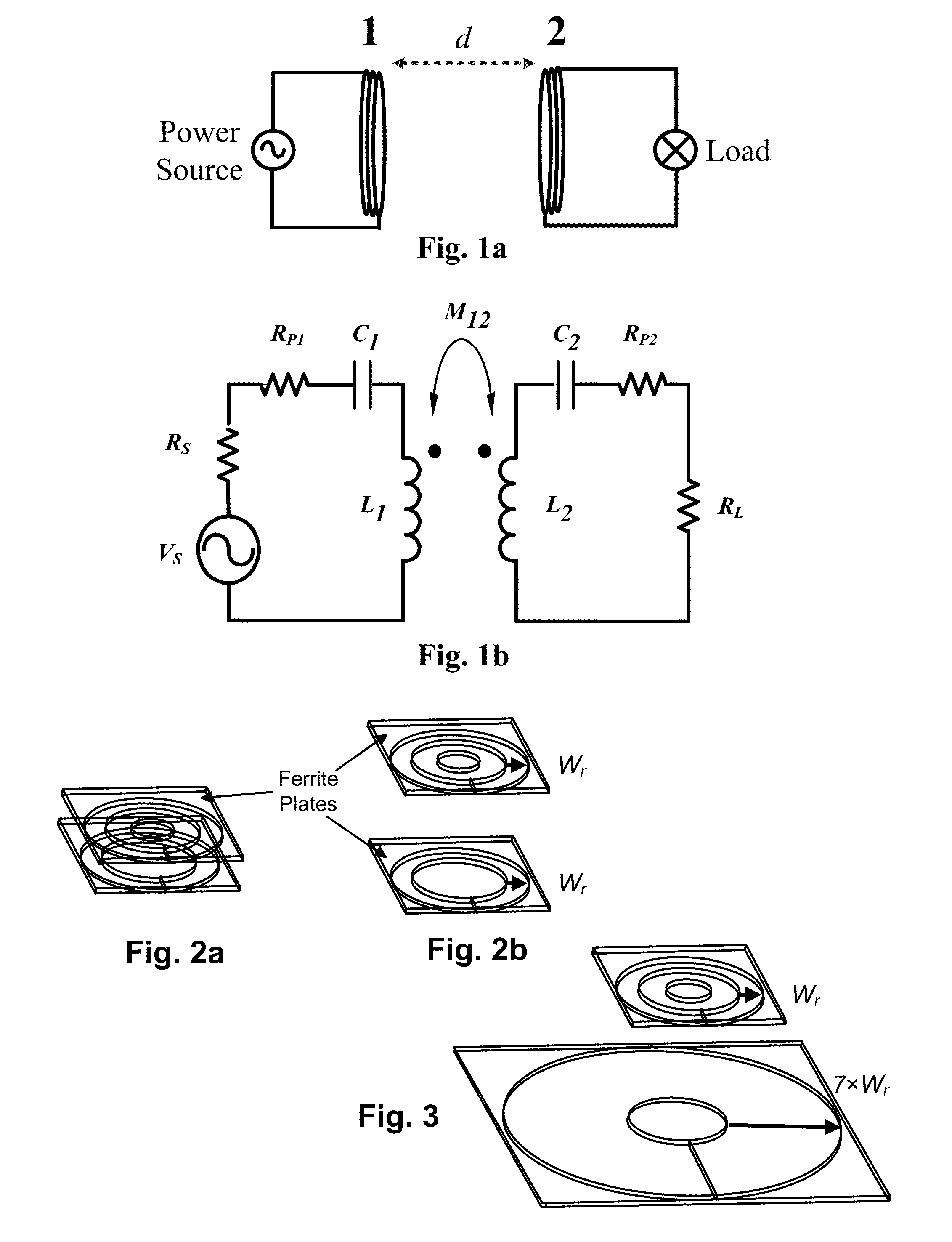
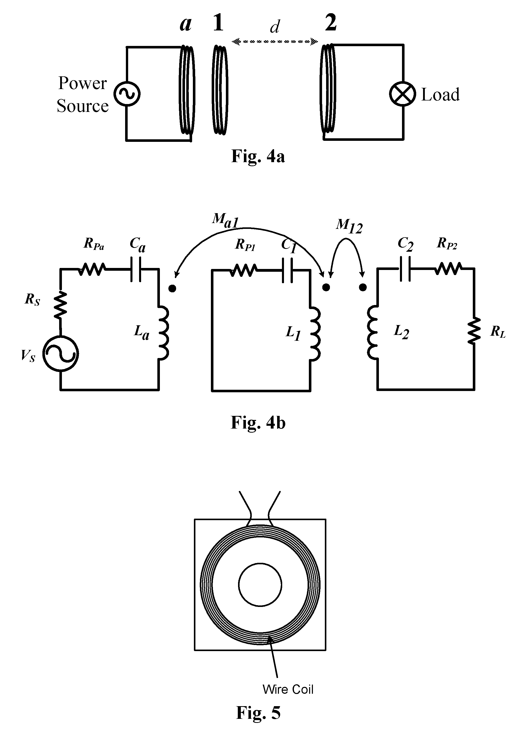
[0060]The specified operating conditions defined by equation (11) can be implemented in a 3-coil system: namely the driver coil (coil-a), the relay coil-resonator (coil-1) and the receiver coil (coil-2). The relay coil-resonator (coil-1) can be placed between the driver coil-a and the receiver coil-2. If preferred, the relay coil-resonator can also be placed on the same plane as the driver coil-a. The latter co-planar arrangement is now used to illustrate some examples.

[0061]Conventional 2-Coil Wireless Power System.

[0062]In this example, the transmission distance is set at 30 mm which is much larger than the 5 mm in a typical wireless charging pad specified in the Qi standard version 1.1. As shown in FIG. 3, Wr is used to represent the coil width of the receiver coil. This coil width is defined as the difference of the outer diameter of the coil and the inner hollow radius of the coil. In this example, the transmitter coil is assumed to have the same inner hollow radius as that of ...


PUM


Abstract

A wireless power charging system includes an intermediate relay coil. In one aspect, a wireless power charging system is designed to charge a separate device having a receiver that includes a receiver coil. The separate device conforms to a specification for the wireless power charging system, which may be a public standard for wireless power charging systems. The wireless power charging system includes a transmitter and a relay coil resonator. The transmitter includes a driver coil that is driven by a power source. The relay coil resonator includes a relay coil that is used to inductively couple power from the driver coil to the receiver coil. The wireless power charging system is designed so that it satisfies Eqn. (11) above.

Description

BACKGROUND[0001]1. Field of the Invention[0002]This invention is related to inductive power transfer, and more specifically to inductive power transfer using a relay coil.[0003]2. Description of the Related Art[0004]Wireless (i.e., inductive) power transfer has drawn renewed interest recently, particularly in the wireless charging of portable electronics products. The formation of the wireless power consortium which promotes the wireless power standard Qi has sped up the research and development of wireless power transfer technology. However, in the Qi standard version 1.1, the distance or gap between the surface of a wireless charging pad (or literally the transmitter coil) and the receiver coil of the load is typically limited to 5 mm. As more varieties of wireless charging systems will certainly appear, it is envisaged that some new wireless charging systems may benefit from a larger or extended gap between the transmitter coil and the receiver coil. For example, the transmitter ...

Claims


Application Information

Patent Timeline
Patent Type & Authority Patents(United States)
IPC IPC(8): H02J7/00H02J5/00
CPCH02J50/10H02J5/005H02J50/12H02J50/50
Inventor LIU, XUN
Owner CONVENIENTPOWER HK
Why Eureka
Try Eureka