Systems, methods, and apparatuses for using a high current switching device as a logic level sensor

a switching device and logic level technology, applied in the field of electric converters, can solve the problems of inconvenient inability to provide satisfactory or reliable operation of replacement electrical devices, and inability to use low-voltage switching devices such as high-current relays or contactors, so as to achieve reliable detection of the operating state of the switching device and preserve energy efficiency

Active Publication Date: 2016-03-15
EXPRESS IMAGING SYST
View PDF250 Cites 15 Cited by
  • Summary
  • Abstract
  • Description
  • Claims
  • Application Information

AI Technical Summary

Benefits of technology

[0010]A load resistor coupled between a high-impedance controller input and ground provides one option for producing sufficient current flow to reliably sense the state of the line voltage switching device while limiting the current flow to a high-impedance controller input. Shunting such a current flow to ground however can generate considerable heat and also reduces the overall efficiency of any electrical load device. Additionally, given the relatively high line voltages typically used to power legacy electrical devices, a resistive device rated for high power and voltage service is needed. Such power resistors can be physically quite large and may continuously generate heat while in operation. Smaller form factor electrical load devices may be unable to physically accommodate such a large power resistor. Additionally, smaller form factor electrical load devices may not be able to adequately dissipate the heat produced by the power resistor thereby unacceptably compromising the performance or operational lifetime of the replacement electrical load device.
[0011]A preferred alternative offering several advantages over simply shunting a portion of current to ground includes permitting sufficient current to flow through the line voltage switching device to reliably detect the operational state of the switching device, returning a significant portion of the current through a “non-dissipative” or similar near-lossless circuit to the electrical load device, and directing a smaller portion of the current at a lower voltage to a high-impedance controller input. Such a solution preserves energy efficiency while providing a signal reliably indicative of the state of the line voltage switching device and compatible with the high-impedance controller input.
[0018]The apparatus may further include at least one second capacitive device that dampens current fluctuations in the second output signal, the at least one second capacitive device electrically coupled in parallel with the second resistive device. The apparatus may further include at least one overvoltage protection device that maintains the second voltage below a defined second voltage threshold, the at least one overvoltage protection device electrically coupled in parallel with the second resistive device and the at least one second capacitive device.

Problems solved by technology

While the one or more environmental sensors used to control the operation of a line voltage switch may be useful for controlling one or more aspects of an energy efficient replacement device, in many instances simply passing a low voltage, low current, signal provided by the environmental sensor through the line voltage contacts of the line voltage switch may not provide satisfactory or reliable operation of the replacement electrical device.
Additionally, a simple replacement of the line voltage switching device with a low voltage switching device is discouraged as cost ineffective since replacement of the line voltage switching device frequently requires replacement of one or more integral or electrically coupled environmental sensors.
The design and materials of construction of the switching devices, and in particular, the electrical contacts used in at least some line voltage switching devices such as high current relays or contactors are unsuitable for low current signaling.
Frequently, the materials or design used successfully in a high voltage application, where robustness may be considered paramount over any inherent resistance of the switching device, are unsuitable for the relatively low currents or voltages encountered in signaling service.
Such relatively low currents may be insufficient to reliably pass through the switching device to provide a satisfactory indication to a control device of the whether the line voltage switching device is in a CLOSED (i.e., electrically continuous) or an OPEN (i.e., electrically discontinuous) state.
Shunting such a current flow to ground however can generate considerable heat and also reduces the overall efficiency of any electrical load device.
Such power resistors can be physically quite large and may continuously generate heat while in operation.
Smaller form factor electrical load devices may be unable to physically accommodate such a large power resistor.
Additionally, smaller form factor electrical load devices may not be able to adequately dissipate the heat produced by the power resistor thereby unacceptably compromising the performance or operational lifetime of the replacement electrical load device.

Method used


Image

  • Systems, methods, and apparatuses for using a high current switching device as a logic level sensor
  • Systems, methods, and apparatuses for using a high current switching device as a logic level sensor
  • Systems, methods, and apparatuses for using a high current switching device as a logic level sensor

Examples


Embodiment Construction

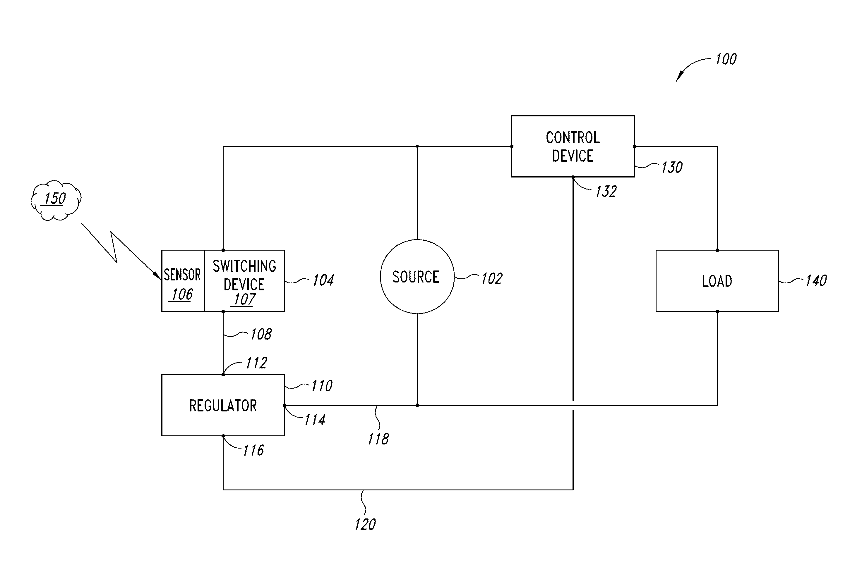
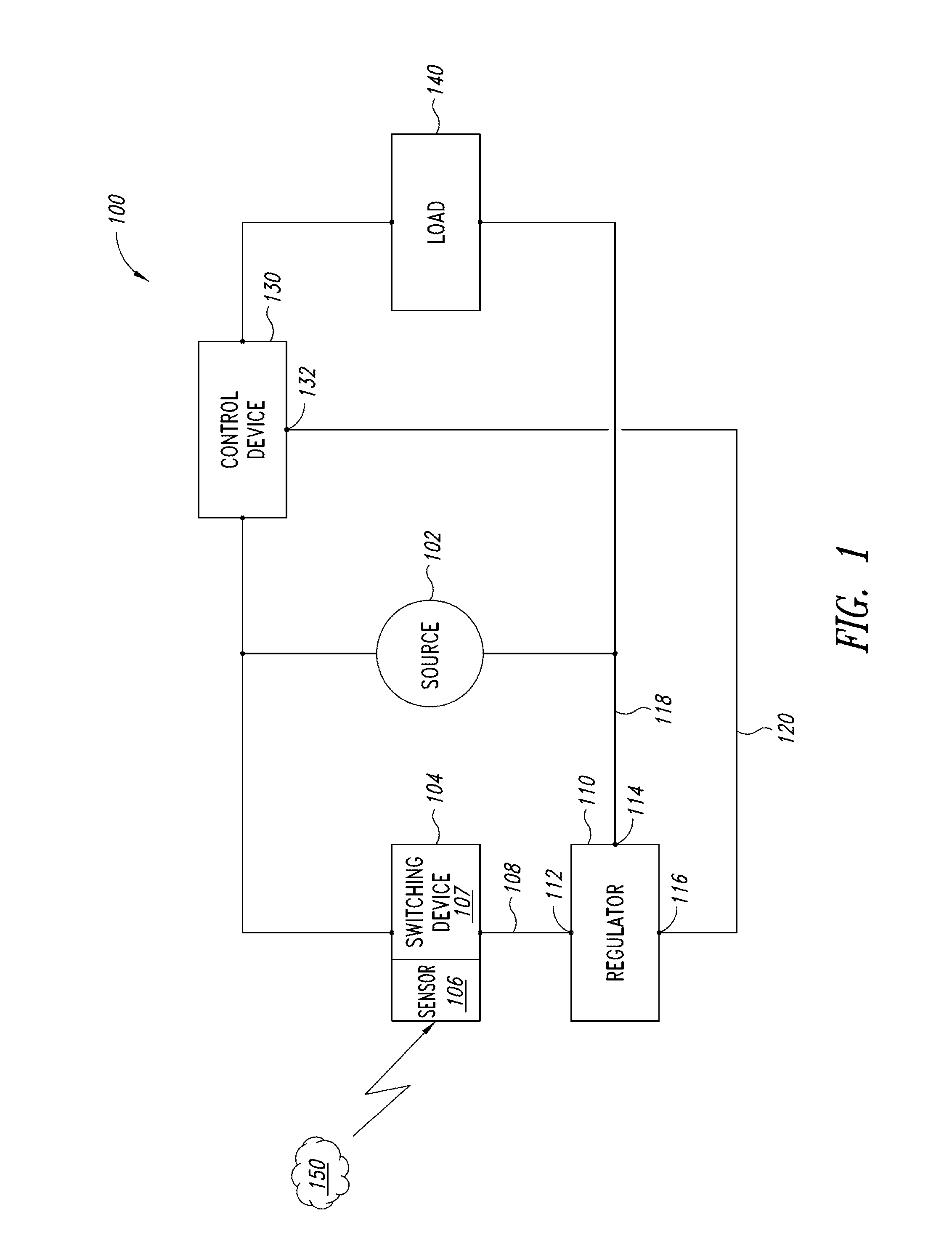
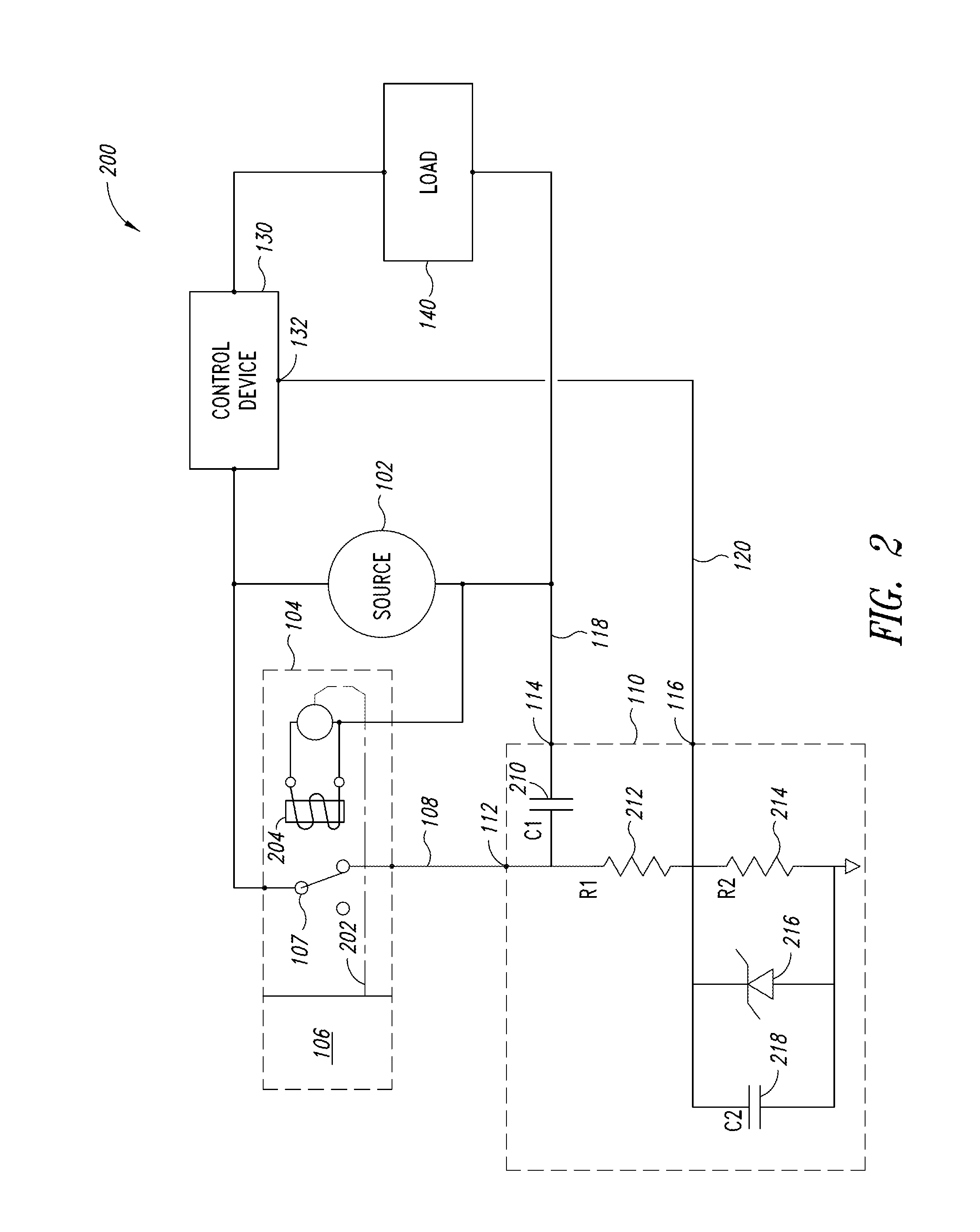
[0026]In the following description, certain specific details are set forth in order to provide a thorough understanding of various disclosed embodiments. However, one skilled in the relevant art will recognize that embodiments may be practiced without one or more of these specific details, or with other methods, components, materials, etc. In some instances, well-known or well-documented electrical components such as capacitive devices, resistive devices, diodes and the like have either not been shown or shown in an abstract manner and have not been described in detail to avoid unnecessarily obscuring descriptions of the embodiments. In other instances, well-known or well documented electronic systems such as environmental sensors, voltage sources, switched-mode power supplies, and solid state lighting devices have either not been shown or shown abstractly and have not described in detail to avoid unnecessarily obscuring descriptions of the embodiments.

[0027]Unless the context requi...


PUM


Abstract

A line voltage signal at a first voltage and a first current supplied by a line voltage switching device responsive to a sensed or detected event can be provided to a first node of a regulator. A portion of the line voltage signal can be passed at the first voltage through a capacitive device in the regulator and provided at a second node for return to an electrical circuit containing a load device. The remaining portion of the line voltage signal can be passed to a voltage divider comprising at least a first resistive device and a second resistive device. A signal output at a second voltage and a second current that is suitable for introduction to a high-impedance controller input can be obtained at a third node electrically coupled to a point between the first resistive device and the second resistive device.

Description

BACKGROUND[0001]1. Technical Field[0002]The present disclosure generally relates to the field of electrical converters and, more particularly, electrical converters that permit the use of a line voltage switching device as an input to a high-impedance controller input.[0003]2. Description of the Related Art[0004]Electrical devices are frequently automated using one or more line voltage switching devices. At times, the line switching device can be coupled to one or more environmental sensors to permit the electrical load controlled by the switching device to respond to the occurrence of one or more events. An example includes electrical devices such as access control arm motors that automatically rise when the motion associated with an approaching vehicle is detected. Another example includes electrical devices such as luminaires that automatically illuminate when a change in ambient light level is detected. Other sensors such as proximity sensors, stress and strain sensors, load cel...

Claims


Application Information

Patent Timeline
Patent Type & Authority Patents(United States)
IPC IPC(8): H05B37/00H02M1/10H05B37/02H05B41/14H05B39/00H02M1/00
CPCH05B37/02H02M1/10H02M2001/0006H05B47/10H02M1/0006
Inventor REED, WILLIAM, G.
Owner EXPRESS IMAGING SYST
Why Eureka
Try Eureka