Re-circulation enhanced electro-optic modulator

a modulator and electromagnetic technology, applied in non-linear optics, instruments, optics, etc., can solve the problem that the modulator can potentially have a large instantaneous modulation bandwidth, and achieve the effects of reducing the applied voltage, reducing the distortion of memory effects, and low loss

Active Publication Date: 2016-03-22
HRL LAB
View PDF11 Cites 16 Cited by
  • Summary
  • Abstract
  • Description
  • Claims
  • Application Information

AI Technical Summary

Benefits of technology

[0013]The presently disclosed modulator has a compact resonator loop the comprises a circular-loop 2×2 MZI and a short feedback recirculation segment, unlike the modulators of Yariv, of Green, et al. and of Sacher and Poon that have a large resonator loop consisting of a linear MZI and long feedback segment. Thus, the FSR of the resonator loop in the presently disclosed modulator is large so the modulator can potentially have large instantaneous modulation bandwidth.
[0014]The presently disclosed modulator can have high modulation efficiency while also having a resonator with large FSR because the insertion loss of its optical waveguides is minimized as a result of its circular configuration. The circular configuration enables the radius of curvature of its optical waveguides to be maximized for a given overall resonator-loop round-trip propagation time. For the presently disclosed modulator, both phase-modulation arms of its MZI preferably follow circular paths that are preferably concentric, that have almost the same radius of curvature and that have almost the same length. The circular path maximizes the radius of curvature of the two optical waveguides comprising the two phase-modulation arms while achieving a given short loop length, to reduce the propagation loss of the light and thus increase the Q of the resonator loop. In contrast to the presently disclosed modulator, the prior modulator of Burns, et al. has a short optical path for only one phase-modulation arm of its MZI but a long optical path for the other phase-modulation arm. The higher optical loss of that long path could degrade the quality factor of the resonator loop and a degraded resonator Q could compromise the degree of reduction of the required modulation voltage that is achieved, as discussed in the article by Yariv as well as in the publication of Burns, et al.
[0018]The presently disclosed modulator has a simpler electronic interface compared to prior modulators that provide push-pull modulation (such as those of Burns, et al. and of Green, et al.) because the presently disclosed modulator has a push-pull traveling-wave electro-optic modulation structure that, because of the design and construction of that electro-optic modulation structure, produces phase modulation of opposite polarity in the two arms of its MZI when a single modulation control voltage waveform is applied to the traveling-wave electrodes. The use of a traveling-wave push-pull modulation structure enables the presently disclosed modulator to be able to be modulated at much higher frequencies. In contrast to the presently disclosed modulator, these prior modulators must achieve push-pull modulation by requiring the modulation-control electronics to provide two separate modulation-control voltages of opposite polarity that are then applied to the two bulk electrodes that control the optical-phase modulation of the two arms of the MZI.

Problems solved by technology

Thus, the FSR of the resonator loop in the presently disclosed modulator is large so the modulator can potentially have large instantaneous modulation bandwidth.

Method used


Image

  • Re-circulation enhanced electro-optic modulator
  • Re-circulation enhanced electro-optic modulator
  • Re-circulation enhanced electro-optic modulator

Examples


Embodiment Construction

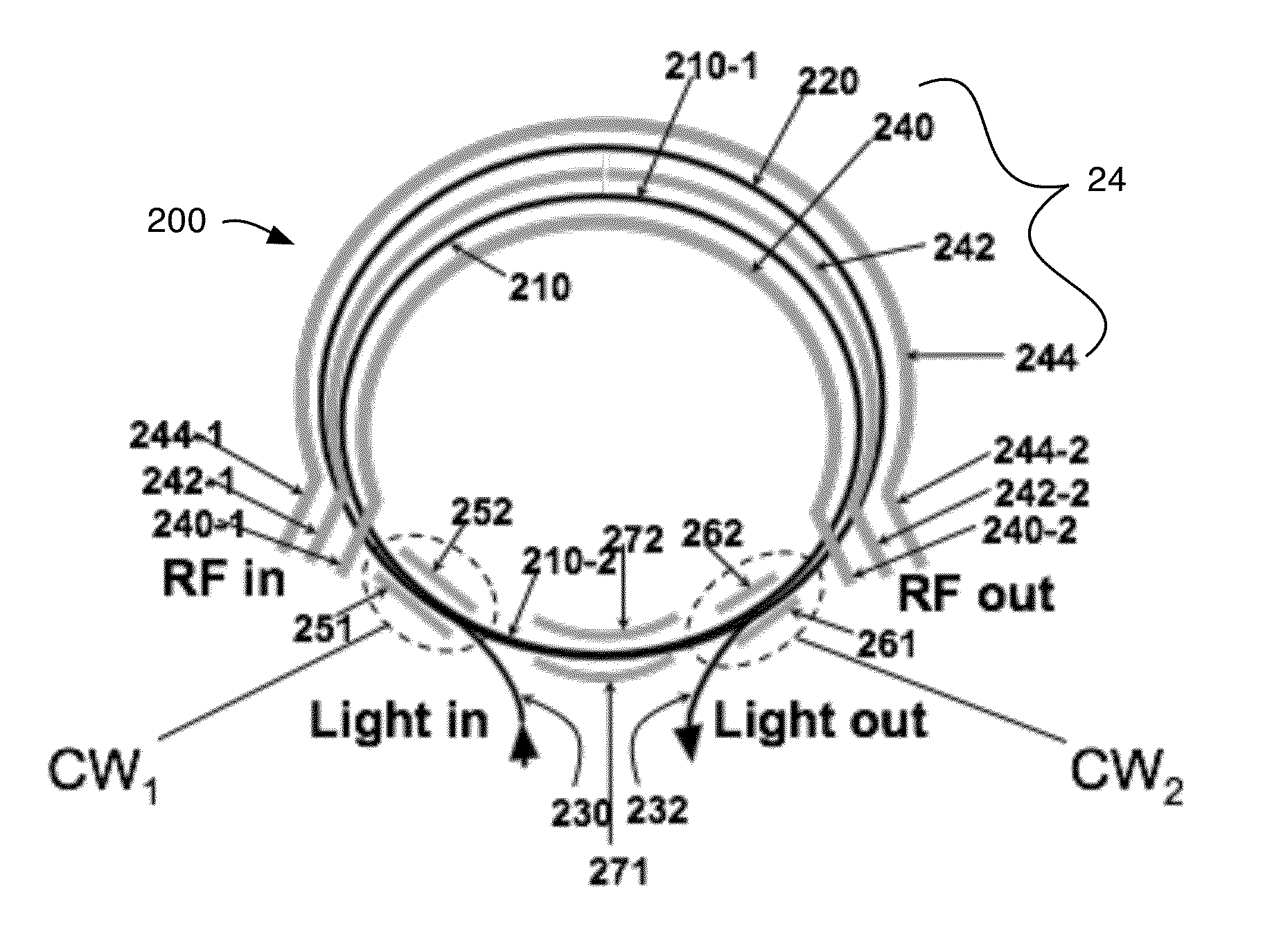
[0030]The presently disclosed electro-optic modulator is depicted schematically in FIGS. 5a-5d. In one embodiment, the disclosed electro-optic modulator 200 comprises a circular-ring optical waveguide 210, a circular optical waveguide segment 220 and two S-curved optical waveguide segments 230 and 232. See FIG. 5a. The circular-ring optical waveguide 210 forms a continuous ring which is circularly shaped in the preferred embodiment. It should be appreciated that waveguide 210 may be formed as a continuous ring configuration of any convenient shape, so it could be of an oval or oval-like configuration or an egg-shaped configuration, if desired. In the following discussion, waveguide 210 will be referred to as a circular-ring waveguide as that is the shape selected for the currently preferred embodiment thereof. Waveguide 210 forms a continuous loop, but for sake of discussion it will sometimes to useful to discuss portions of it. The upper portion of waveguide 210 in FIG. 5a is label...


PUM

PropertyMeasurementUnit
frequenciesaaaaaaaaaa
refractive indexaaaaaaaaaa

Abstract

An optical modulator includes a waveguide Mach-Zehnder interferometer having a first and a second input and a first and a second output, a feedback waveguide segment connecting the second output with the second input, and a traveling-wave electrode; wherein the Mach-Zehnder interferometer, feedback waveguide segment and traveling-wave electrode are substantially arranged at or adjacent the perimeter of a smooth curve defining a closed geometric figure, the traveling-wave electrode extending along at least 50% of the length of the perimeter of the smooth curve.

Description

CROSS REFERENCE TO RELATED APPLICATIONS[0001]This application is related to U.S. provisional patent Application 61 / 727,632 filed on the same date as this application and entitled “Electro-optic Modulation Structures”, the disclosure of which is hereby incorporated herein by reference.TECHNICAL FIELD[0002]This application relates to electro-optic modulators.BACKGROUND[0003]Electro-optic modulators are well known and one of the well-known deficiencies of electro-optic modulators is the inefficient transduction from the electrical signal to the modulated optical signal. This weakness arises because the needed modulation-control voltage of prior art modulators is so high; generally at least several volts is needed to achieve full on-off modulation. Optical ring resonators and optical disk resonators based on whispering-gallery modes propagating near the perimeter of the disks have been used in prior electro-optic modulators as a means to reduce the needed modulation-control voltage.[000...

Claims


Application Information

Patent Timeline
Patent Type & Authority Patents(United States)
IPC IPC(8): G02F1/35G02F1/01G02F1/035
CPCG02F1/011G02F1/0356G02F1/21G02F1/035G02F2201/127G02F2202/20G02F2203/50G02F1/2257
Inventor YAP, DANIEL
Owner HRL LAB
Why Eureka
Try Eureka