Wireless battery area network for a smart battery management system

a battery management system and wireless technology, applied in secondary cells, battery service/maintenance, instruments, etc., can solve the problems of high cost and high power consumption, inability to scale up the current bms architecture to handle such a large number of battery cells, and inability to accurately configure the battery operation directly. , to achieve the effect of extending the life cycle of the battery pack, facilitating the scalability of large-scaled battery applications, and accurately extending the battery life cycl

Active Publication Date: 2016-03-22
NAVITAS SOLUTIONS
View PDF42 Cites 44 Cited by
  • Summary
  • Abstract
  • Description
  • Claims
  • Application Information

AI Technical Summary

Benefits of technology

[0008]A system and method is disclosed for smartly monitoring and controlling individual batteries within a large-scaled battery application. The system can link a plurality of batteries to a master battery management unit (M-BMU) by establishing a wireless battery area network within a battery pack. The method can include the monitoring of individual battery operations for the voltage, current, temperature, or impedance, and the control of its operation by balancing or bypassing the battery. The monitoring and control of each battery operation is preferably performed by a slave battery management unit (S-BMU) that is mounted directly on each battery cell. State-of-charge (SoC) and state-of-health (SoH) algorithms are executed at the M-BMU. The data protocol for monitoring and controlling cells is transmitted between the S-BMUs and the M-BMU at a predefined periodic rate. Such a wireless battery area network can easily provide the scalability for large-scaled battery applications. In addition, a wireless battery area network can accurately configure battery operation directly for a corresponding battery cell, thus extending the battery pack's life cycle.

Problems solved by technology

However, current BMS architecture is not scalable to handle such a large number of battery cells.
More importantly, the complexity and cost of wire harnesses for handling large-scaled battery applications is often not acceptable.
Also, conventional battery management systems require data bus isolators such as an opto-coupler based vertical bus, and suffer from high cost and high power consumption.

Method used


Image

  • Wireless battery area network for a smart battery management system
  • Wireless battery area network for a smart battery management system
  • Wireless battery area network for a smart battery management system

Examples


Embodiment Construction

[0023]During the course of this description, like numbers will be used to identify like elements according to the different figures which illustrate the invention.

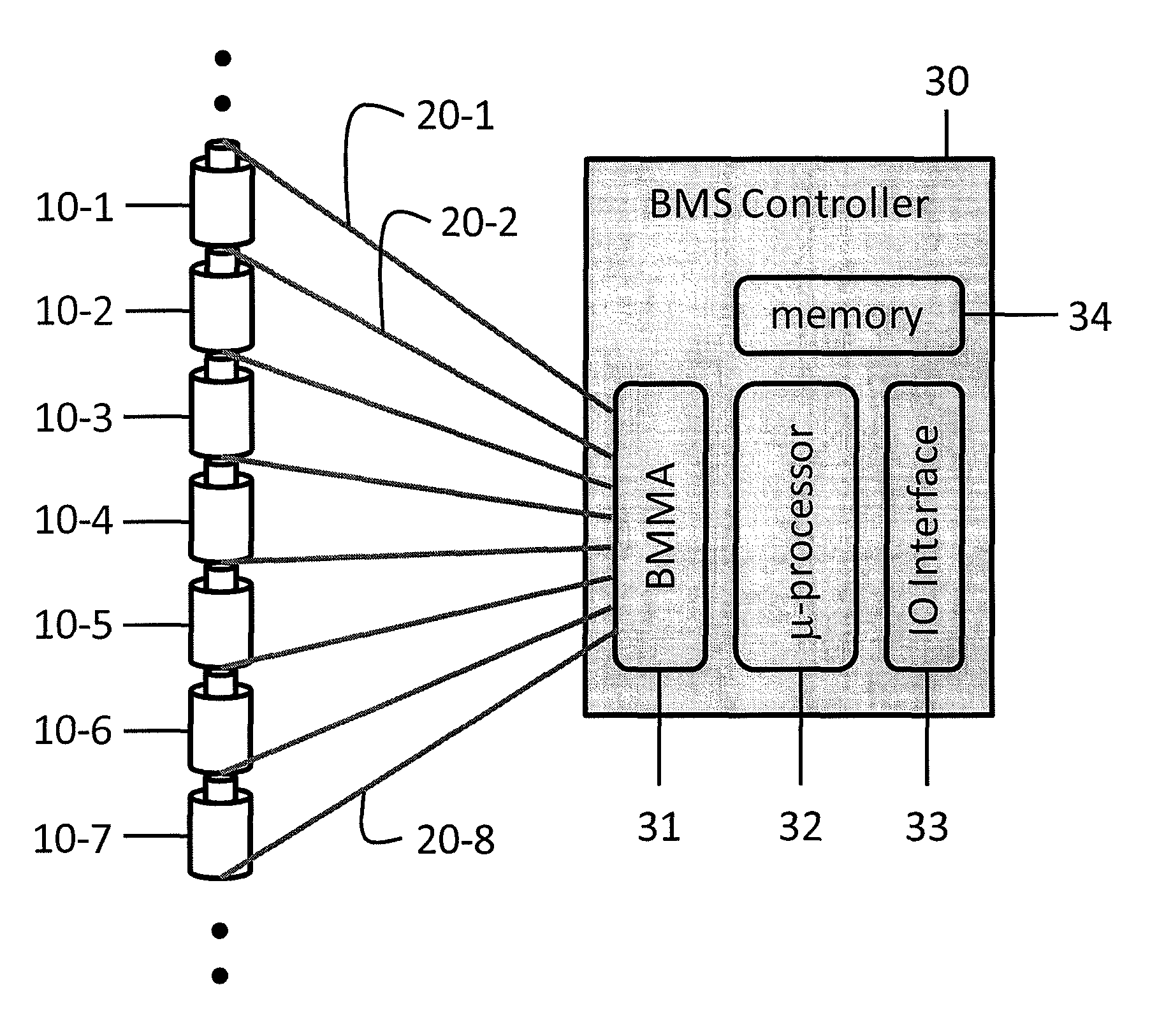
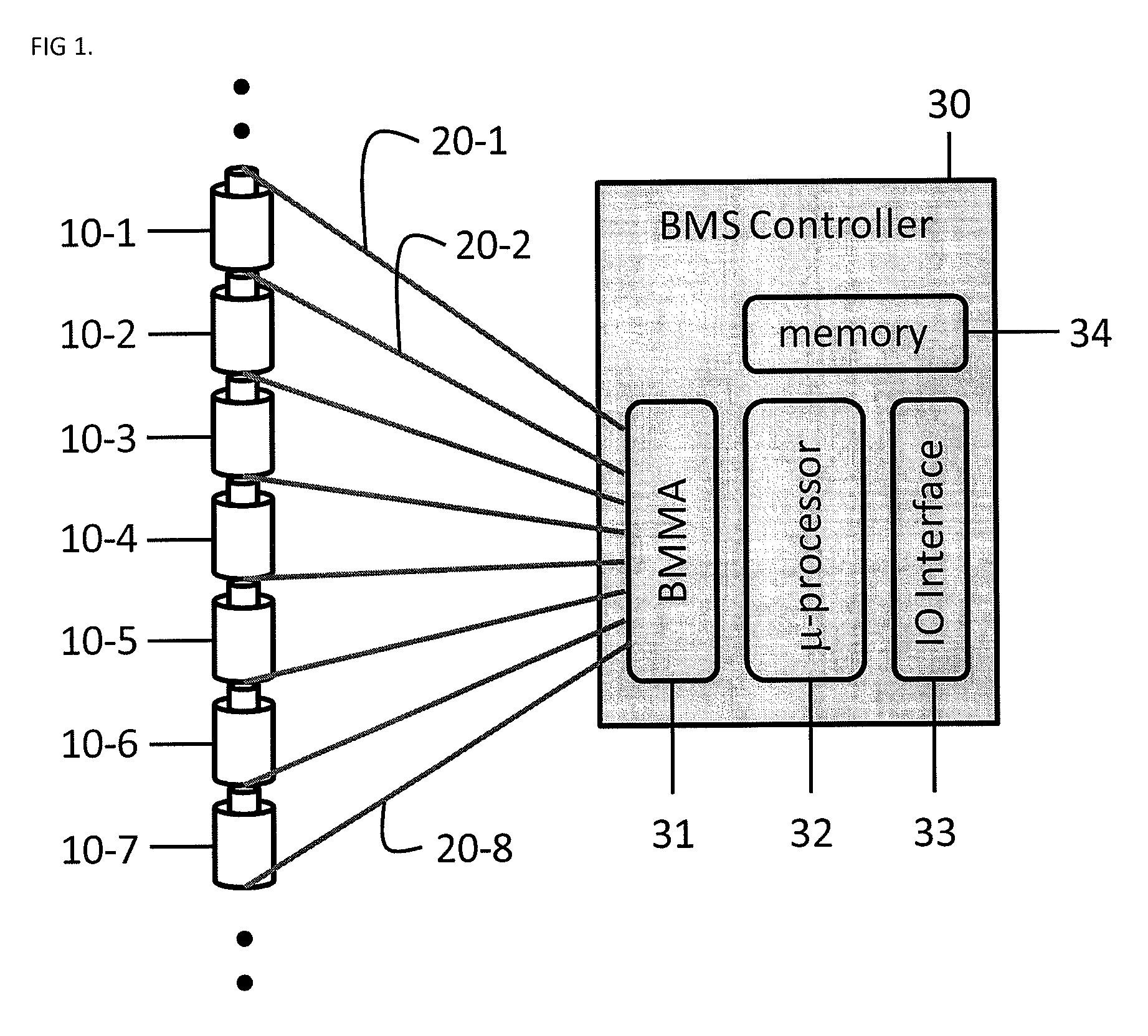
[0024]In general, all Battery Management Systems (BMS) are implemented using an electronic circuit board. The BMS monitors the voltage, the current, impedance, and the temperature of each cell. Since a BMS has to monitor each and every Li-Ion battery cell, the typical prior art BMS board needs to be wired to every Li-Ion cell. This can be a problem if the number of Li-Ion battery cells to be monitored needs to increase. According to the prior art, hierarchical BMS architectures are often used, however, the use of BMS architectures also calls for an increase in the number of BMS boards and the overall cost. When the number of Li-Ion cells increases to a few hundred, or up to thousands, which is often the case for electric vehicle (EV) or power plant applications, the wire harness becomes a serious problem. Thus, one of the ...


PUM

PropertyMeasurementUnit
state-of-chargeaaaaaaaaaa
chargeaaaaaaaaaa
over voltageaaaaaaaaaa

Abstract

A Wireless battery area network permits the wirelessly monitoring and controlling of individual batteries within large-scale battery applications. The system automatically configures its wireless nodes in the network and provides for the linking of a plurality of batteries (10) to a master battery management unit (M-BMU) (100) by establishing a wireless battery area network within a battery pack that include slave units (S-BMU) (210). The entire system may also be controlled by a top level battery management unit (T-BMU) (510). The system and method allows for the monitoring of voltage, current, temperature, or impedance of individual batteries and for the balancing or bypassing of a battery.

Description

CROSS-REFERENCE TO RELATED APPLICATIONS[0001]This application is the National Phase filing of PCT Application No. PCT / US2011 / 058503 filed Oct. 31, 2011 and claims priority to U.S. Provisional Application No. 61 / 409,290, the disclosure of which is hereby incorporated by reference in its entirety.BACKGROUND OF THE INVENTION[0002]1. Field of the Invention[0003]The invention relates to a battery management system including a plurality of battery cells in a battery pack in which a wireless battery area network is automatically established between a base station (M-BMU) and a plurality of slave battery cell sensor nodes (S-BMU).[0004]2. Description of Related Art[0005]Lithium-ion (Li-ion) batteries are growing in popularity as energy storage reservoirs for industrial and automotive applications, high-voltage energy uses (smart grid), such as wind turbines, photo-voltaic cells, and hybrid electric vehicles, and this has spurred demand for safer, higher performing battery monitoring and pro...

Claims


Application Information

Patent Timeline
Patent Type & Authority Patents(United States)
IPC IPC(8): H02J7/00H04Q9/00H01M10/46H01M10/44H01M10/42G01R31/36
CPCH02J7/0057H01M10/4207H01M10/441H01M10/46H02J7/0021H04Q9/00G01R31/3689H04Q2209/43H04Q2209/47G01R31/371H02J7/0048H02J7/005H02J7/0019H02J7/00H02J7/0069
Inventor LEE, JAESIKLEE, INSEOPLEE, MINKYUCHON, ANDREW M.
Owner NAVITAS SOLUTIONS
Why Eureka
Try Eureka