
Method and apparatus for testing integrated circuits

a technology of integrated circuits and integrated circuits, applied in the direction of testing circuits, instruments, nuclear elements, etc., can solve the problems of reducing the cost of ic testing, ic manufacturers and tester vendors rethinking how ic testing should be performed, and the projected cost of testers will continue to rise dramatically in the near future, so as to simplify the overall test usage, simplify the problem of cross-platform incompatibility, and reduce the effect of effor

Active Publication Date: 2008-10-14
ADVANTEST CORP
View PDF17 Cites 17 Cited by
  • Summary
  • Abstract
  • Description
  • Claims
  • Application Information

AI Technical Summary

Benefits of technology

This approach simplifies tester usage, reduces development efforts, and lowers test costs by enabling the reuse of test solutions and optimal resource allocation for diverse IC testing requirements, while addressing cross-platform incompatibilities and inefficiencies.

Problems solved by technology

The increasing complexity of System-on-a-Chip (SOC) devices and the simultaneous demand for a reduction in the cost of chip testing has forced both IC manufacturers and tester vendors to rethink how IC testing should be performed.
According to industry studies, without re-engineering the projected cost of testers will continue to rise dramatically in the near future.
A major reason for the high cost of test equipment is the specialized nature of conventional tester architecture.
Each tester manufacturer has a number of tester platforms that are not only incompatible across companies such as Advantest, Teradyne and Agilent, but also incompatible across platforms such as the T3300, T5500 and T6600 series testers manufactured by Advantest.
Because of these incompatibilities, each tester requires its own specialized hardware and software components that cannot be used on other testers.
In addition, a significant translation effort is required to port a test program from one tester to another, and third party solutions are difficult to develop.
Even when a third party solution is developed for a platform, it cannot be ported or reused on a different platform.
The translation process from one platform to another is generally complex and error prone, resulting in additional effort, time and increased test cost.
A major reason for the high cost of test equipment is the specialized nature of conventional tester architecture.
Each tester manufacturer has a number of tester platforms that are not only incompatible across companies such as Advantest, Teradyne and Agilent, but also incompatible across platforms manufactured by the same company, such as the T3300, T5500 and T6600 series testers manufactured by Advantest.
Because of these incompatibilities, each tester requires its own specialized hardware and software components that cannot be used on other testers.
In addition, a significant translation effort is required to port a test program from one tester to another, and third party solutions are difficult to develop.
Even when a third party solution is developed for a platform, it cannot be ported or reused on a different platform.
The translation process from one platform to another is generally complex and error prone, resulting in additional effort, time and increased test cost.
At the same time, for a given IC, the tester may not provide the most desirable resources that are suitable for that IC.
For example, a logic tester that is suitable to test a complex SoC A that contains an embedded microcontroller, large embedded DRAM and flash, and various other cores such as PCI and USB etc., may be found inadequate for an ASIC B that does not have an embedded microcontroller and large embedded DRAM / flash, but includes DACs and Sigma-Delta converters.
However, because of the specialized nature of conventional test systems and the proprietary nature of the data format in each vendor's equipment, it is frequently impossible to plug-in and use equipment from another vendor.

Method used


Image

  • Method and apparatus for testing integrated circuits
  • Method and apparatus for testing integrated circuits
  • Method and apparatus for testing integrated circuits

Examples


Embodiment Construction

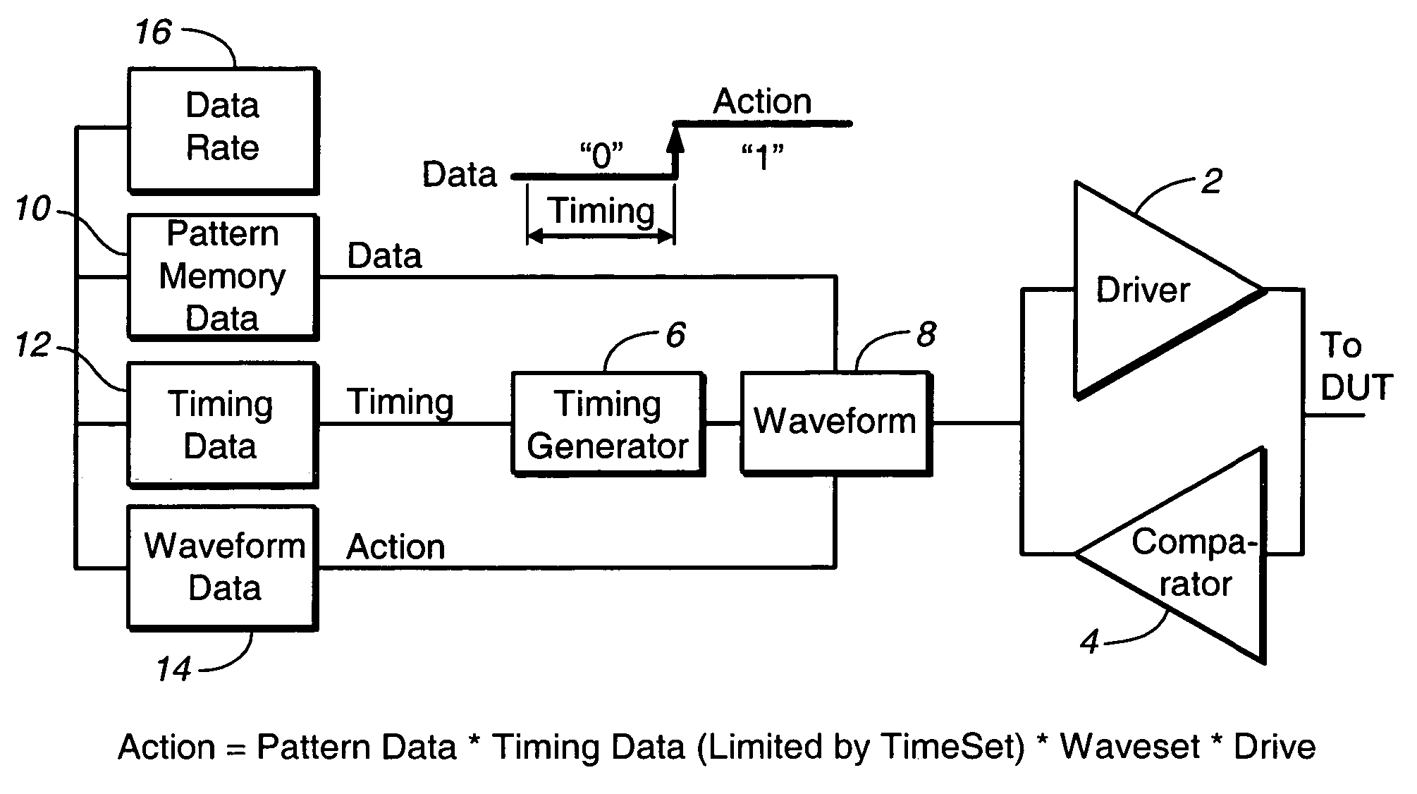
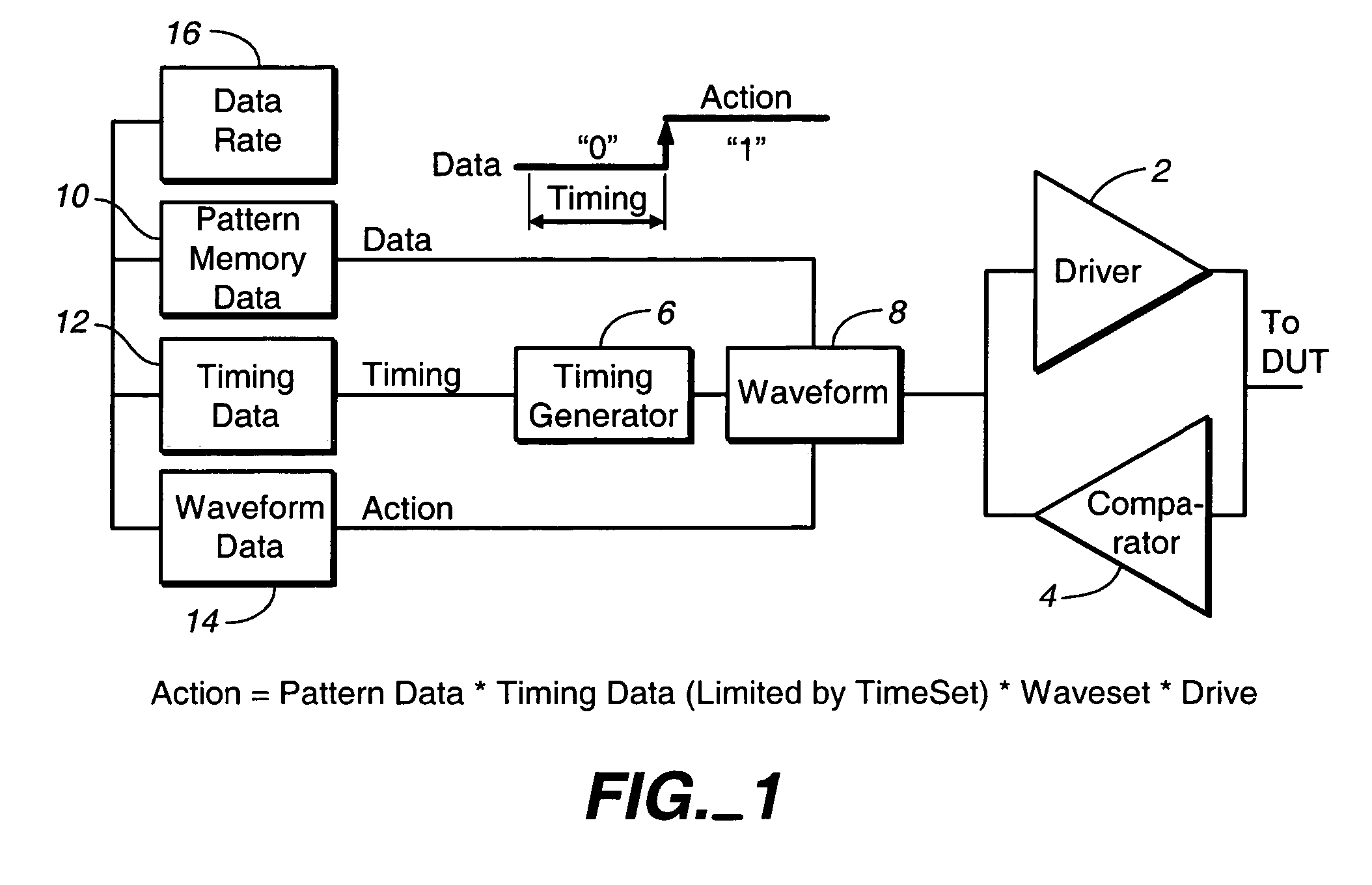
[0037]FIG. 1 illustrates a generalized architecture of a conventional tester showing how a signal is generated and applied to a device-under-test (DUT). Each DUT input pin is connected to a driver 2 that applies test data, while each DUT output pin is connected to a comparator 4. In most cases, tri-state driver-comparators are used so that each tester pin (channel) can act either as an input pin or as an output pin. The tester pins dedicated to a single DUT collectively form a test site that works with an associated timing generator 6, waveform generator 8, pattern memory 10, timing data memory 12, waveform memory data 14, and block 16 that defines the data rate.

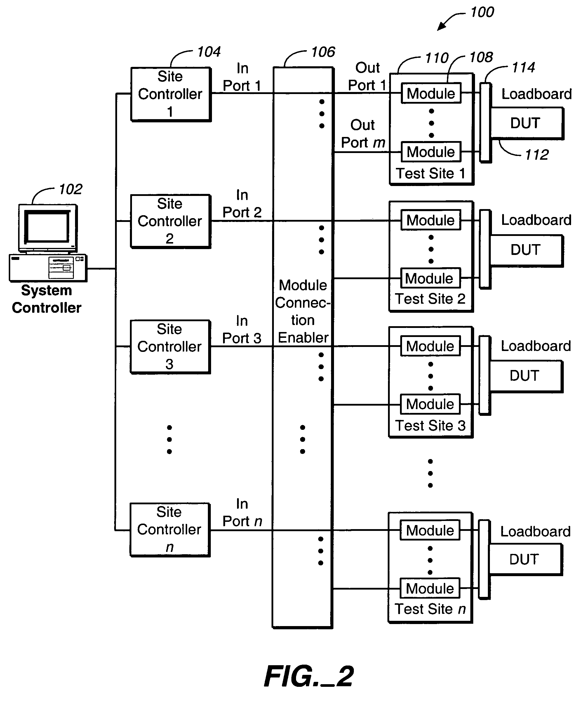
[0038]FIG. 2 illustrates a system architecture 100 according to an embodiment of the present invention. A system controller (SysC) 102 is coupled to multiple site controllers (SiteCs) 104. The system controller may also be coupled to a network to access associated files. Through a module connection enabler 106, each site con...


PUM


Abstract

A distributed operating system for a semiconductor test system, such as automated test equipment (ATE), is described. The operating system includes a host operating system for enabling control of one or more site controllers by a system controller. One or more local operating systems, each associated with a site controller, enable control of one or more test modules by an associated site controller. Each test module performs testing on a corresponding device-under-test at a test site.

Description

CROSS-REFERENCE TO RELATED APPLICATIONS[0001]This application claims the benefit of application No. 60 / 449,622, “Method and Apparatus for Testing Integrated Circuits,” filed Feb. 24, 2003; application No. 60 / 447,839, “Method and Structure to Develop a Test Program for Semiconductor Integrated Circuits,” filed Feb. 14, 2003; U.S. application Ser. No. 10 / 404,002, “Test emulator, test module emulator, and record medium storing programs therein, ” filed Mar. 31, 2003; and U.S. application Ser. No. 10 / 403,817, “Test Apparatus and Test Method,” filed Mar. 31, 2003, all of which are incorporated herein in their entirety by reference. This application also incorporates by reference in its entirety U.S. application Ser. No. 10 / 772,434, “Method and Structure to Develop a Test Program for Semiconductor Integrated Circuits,” filed concurrently herewith, which claims the benefit of application No.60 / 447,839,“Method and Structure to Develop a Test Program for Semiconductor Integrated Circuits,” f...

Claims


Application Information

Patent Timeline
Patent Type & Authority Patents(United States)
IPC IPC(8): G01R27/28G01R31/3183G01R31/319
CPCG01R31/3183G01R31/318307G01R31/318342G01R31/31907
Inventor PRAMANICK, ANKANELSTON, MARKCHEN, LEONSAUER, ROBERT
Owner ADVANTEST CORP
Learn More