Structured packing and method

a structured packing and packing method technology, applied in the direction of liquefaction, separation processes, lighting and heating apparatus, etc., can solve the problems of flooding, electrical power consumption, and the pressure to which the incoming air is required, and achieve the limitation at which the packing will no longer function

Active Publication Date: 2016-03-29
PRAXAIR TECH INC
View PDF7 Cites 21 Cited by
  • Summary
  • Abstract
  • Description
  • Claims
  • Application Information

AI Technical Summary

Benefits of technology

[0015]In any case, in the present invention, unlike the prior art, the arcuate corrugations of the transition region is located internally within the packing itself. Consequently, the advantages of having an end modification that is at right angles to the edge of the packing sheet are realized. At the same time, by the time the upflow of vapor has reached the internal curved transition region of the present invention, its superficial velocity has decreased due to its interaction with the concurrent flow of liquid further decreasing pressure drop within the packing itself and therefore, providing less resistance to the flow of vapor and liquid at the edge of the packing sheet. A further advantage of the present invention is that the arcuate corrugations within the transition region act to relive stress produced by overlying packing layers that would otherwise be intensified by a sharp change in direction of the corrugations from the acute angle to the right angle.
[0016]In a structured packing in accordance with the present invention, the end regions and the transition regions can be first end regions and first transition regions. In such case, the corrugations of the rectangular sheet have second end regions and second transition regions identical to the first end regions and the first transition regions and with the second transition regions configured as a mirror image of the first transition regions. The straight, parallel sections of the corrugations of the second end regions extend from the other of the two opposite edges of each of the sheets and the arcuate sections of the corrugations of the second transition regions connect the straight, parallel sections of the corrugations of the second end region and the main region at the opposite ends thereof. In connection with a method of the present invention, the descending liquid and ascending vapor phases are passed through second end regions and second transition regions of the corrugations of the rectangular sheets.
[0017]Moreover, in a structured packing of the present invention or a method of the present invention using such structured packing, each of the apices can be curved and each of the corrugations can have a triangular, transverse cross-section with two equal sides connected by the curved apices. Further, each of the straight, parallel sections of the corrugations within the end regions can have a length equal to about a corrugation width of the corrugations multiplied by a constant within a range between 0.3 and 4.0 and the arcuate sections of the corrugations within the transition regions can each have a radius in a range of between about 25.0 percent and about 75.0 percent of the corrugation width. Preferably, the radius of curvature can be about 50.0 percent of the corrugation width and the constant can be between 1.0 and 3.0. More preferably, the constant is 2.0 and the length is no less than about 1.27 cm. and no greater than about 3.81 cm. In any embodiment or aspect of the resent invention, the acute angle of the corrugations within the main region can be one of 40 degrees and 45 degrees.

Problems solved by technology

The lower pressure drop within the low pressure column with the use of such structured packings, as opposed to trays, decreases the pressure to which the incoming air is required to be compressed and therefore, also the electrical power consumption.
In structured packing, as well as any mass transfer contacting element, flooding represents a limitation at which the packing will no longer function.
The reason for this is that as the liquid flow in a downward direction through the packing is impeded as a result of excessive upflowing vapor, the liquid begins to build up at the interface between packing layers resulting in the rapid rise in pressure drop leading to flooding.
Column sizes and diameters will have a direct effect on the fabrication costs of the plant.

Method used


Image

  • Structured packing and method
  • Structured packing and method
  • Structured packing and method

Examples


Embodiment Construction

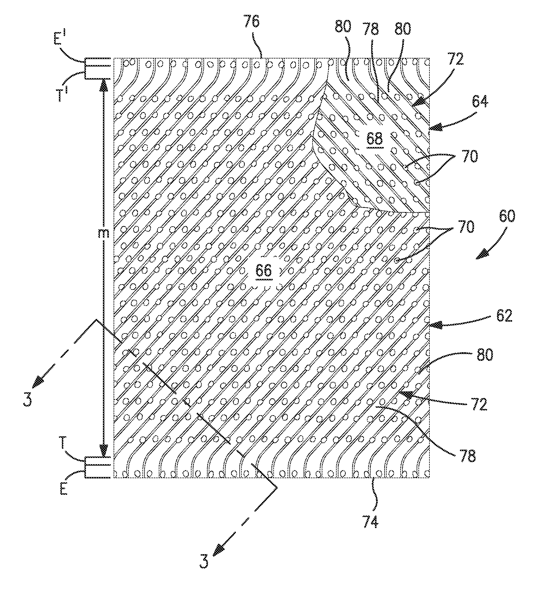
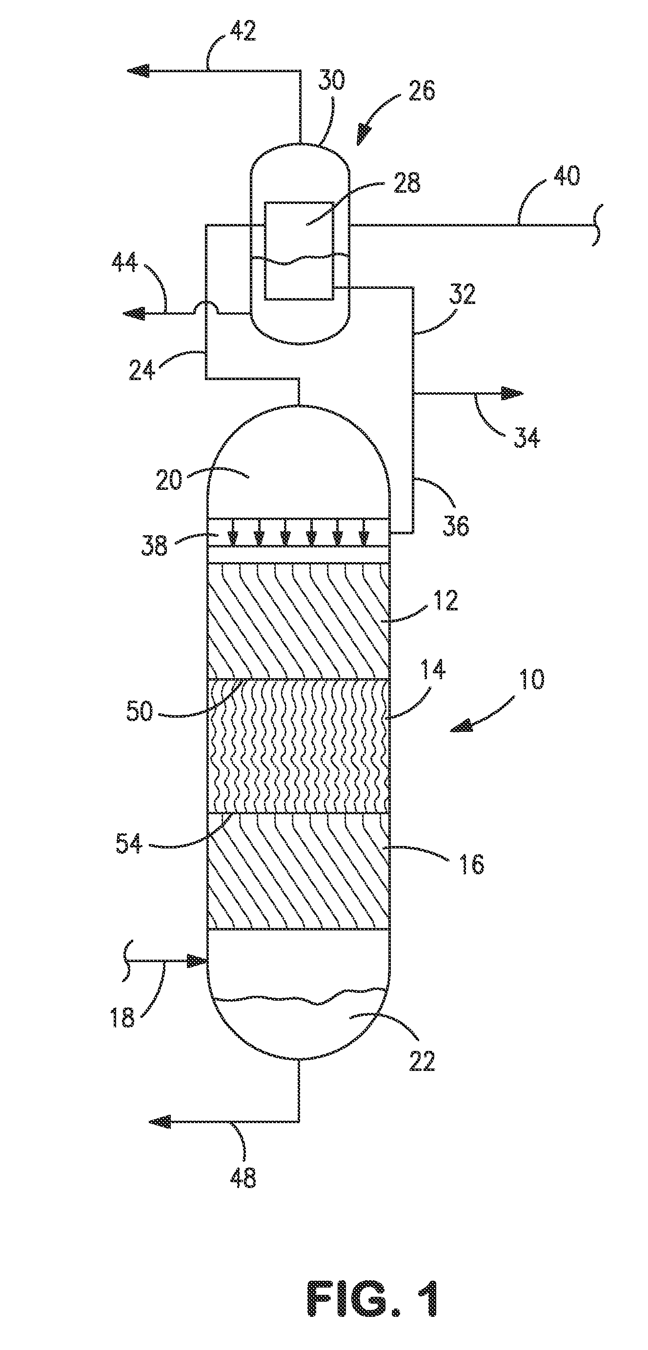
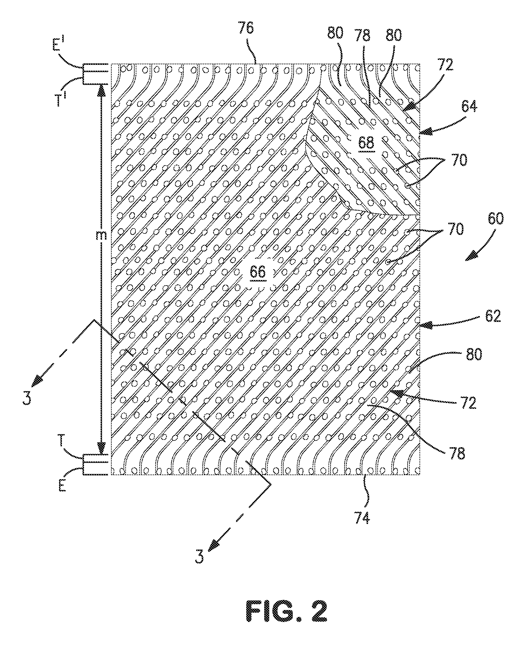
[0026]With reference to FIG. 1, for exemplary purposes only; and not by way of limitation, a distillation column 10 is illustrated that incorporates layers of structured packing in accordance with the present invention that are designated by reference numbers 12, 14 and 16. As illustrated, the rectangular sheets making up layer 14 is oriented at right angles to those of layers 12 and 16.

[0027]In operation, a feed stream 18 containing components of a mixture to be rectified is introduced into the base of distillation column 10 to initiate the formation of an ascending vapor phase that is intimately contacted, within layers 12, 14 and 16 with a descending vapor phase. This contact results in a column overhead vapor 20 that is rich in the more volatile components of the mixture to be separated and a column bottoms liquid 22 that is rich in the less volatile components of the mixture. A vapor column overhead stream 24, composed of the column overhead vapor 20 is introduced into a conden...


PUM


Abstract

A structured packing formed of a plurality of corrugated, rectangular sheets and a method relating to the use thereof. End regions of the corrugations are provided with straight, parallel corrugations extending inwardly from opposed edges of the sheets and a right angles thereto to reduce pressure drop at the interfaces between packing layers and thereby increase hydraulic capacity. Contact is promoted between descending liquid and ascending vapor phases within a main region of the corrugations that have straight, parallel sections of the corrugations oriented at an acute angle to the opposed edges. Transition regions having arcuate sections of the corrugations connect corrugations within the main and end regions to reduce internal pressure drop within the structured packing and thereby further reduce pressure drop at the interfaces and further increase the hydraulic capacity.

Description

FIELD OF THE INVENTION[0001]The present invention relates to a structured packing and a method of using such structured packing in which the structured packing is formed from a plurality of rectangular sheets arranged in a juxtaposed relationship and having a repeating undulating pattern of corrugations that cross one another in adjacent sheets. More particularly, the present invention relates to such a structured packing and method in which the corrugations of each of the sheets have end regions where the corrugations are at right angles to an edge of the sheet, main regions where the corrugations are oriented at an acute angle to the edges of the sheet and transition regions, connecting corrugations within the end and main regions and having corrugations of arcuate configuration.BACKGROUND OF THE INVENTION[0002]Structured packings have long been used as mass transfer contacting elements for such purposes as conducting distillation and absorption processes. A key advantage of struc...

Claims


Application Information

Patent Timeline
Patent Type & Authority Patents(United States)
IPC IPC(8): B01D3/00B01J19/32F25J3/02B01D3/16
CPCB01D3/008B01J19/32B01D3/16B01J2219/3221B01J2219/32206B01J2219/32213B01J2219/32217B01J2219/32227B01J2219/32244B01J2219/32258B01J2219/32272F25J3/028F25J3/04909
Inventor CHEN, GUANG, X.LARSON, KIRK, FREDERICK
Owner PRAXAIR TECH INC
Why Eureka
Try Eureka