
Substrate with antireflection coating and method for producing same

a technology of anti-reflection coating and substrate, which is applied in the direction of vacuum evaporation coating, optical elements, instruments, etc., can solve the problems of high wear stress, ablation of the coating, and long scratches in the coating, so as to reduce the anti-reflection effect, reduce the method, and ensure the effect of durability

Active Publication Date: 2016-03-29
SCHOTT AG
View PDF45 Cites 19 Cited by
  • Summary
  • Abstract
  • Description
  • Claims
  • Application Information

AI Technical Summary

Benefits of technology

This patent is about a coating that reduces reflection of light from surfaces. The coating is made up of layers with a lower refractive index and a higher refractive index. The lower refractive index layers are made of silicon oxide with a small amount of aluminum, which helps achieve good antireflection. The aluminum doping should not exceed a certain level to maintain the desired effect. The higher refractive index layers can also be made of aluminum-containing silicon nitride layers. The method for depositing all layers is simple, as it can be done with a change of the target. The ratios of silicon and aluminum in the layers should be followed to achieve the desired effect. Overall, this patent provides a simple method for achieving effective antireflection coating.

Problems solved by technology

However, depending on the intended use of the substrate, the antireflection coating might be exposed to high wearing stresses.
For example, an outer coating of a vehicle front window, while driving, is exposed to sand and dust particles impinging thereon with a high speed which may result in ablation of the coating over time.
A particular stress to such front windows results when a wiper passes over the soiled front window.
In this way, long scratches can be formed in the coating.
Scratches and other damage cause turbidity and therefore counteract the purpose of an antireflection coating.
In addition, the driver's vision is impaired.
A disadvantage thereof is that the low refractive index silicon oxide layer is very soft compared to the high refractive index materials, especially compared to Si3N4.
So it is just the top layer that still tends to wear quickly.
This results in a reversion of the antireflection effect.

Method used


Image

  • Substrate with antireflection coating and method for producing same
  • Substrate with antireflection coating and method for producing same
  • Substrate with antireflection coating and method for producing same

Examples


Embodiment Construction

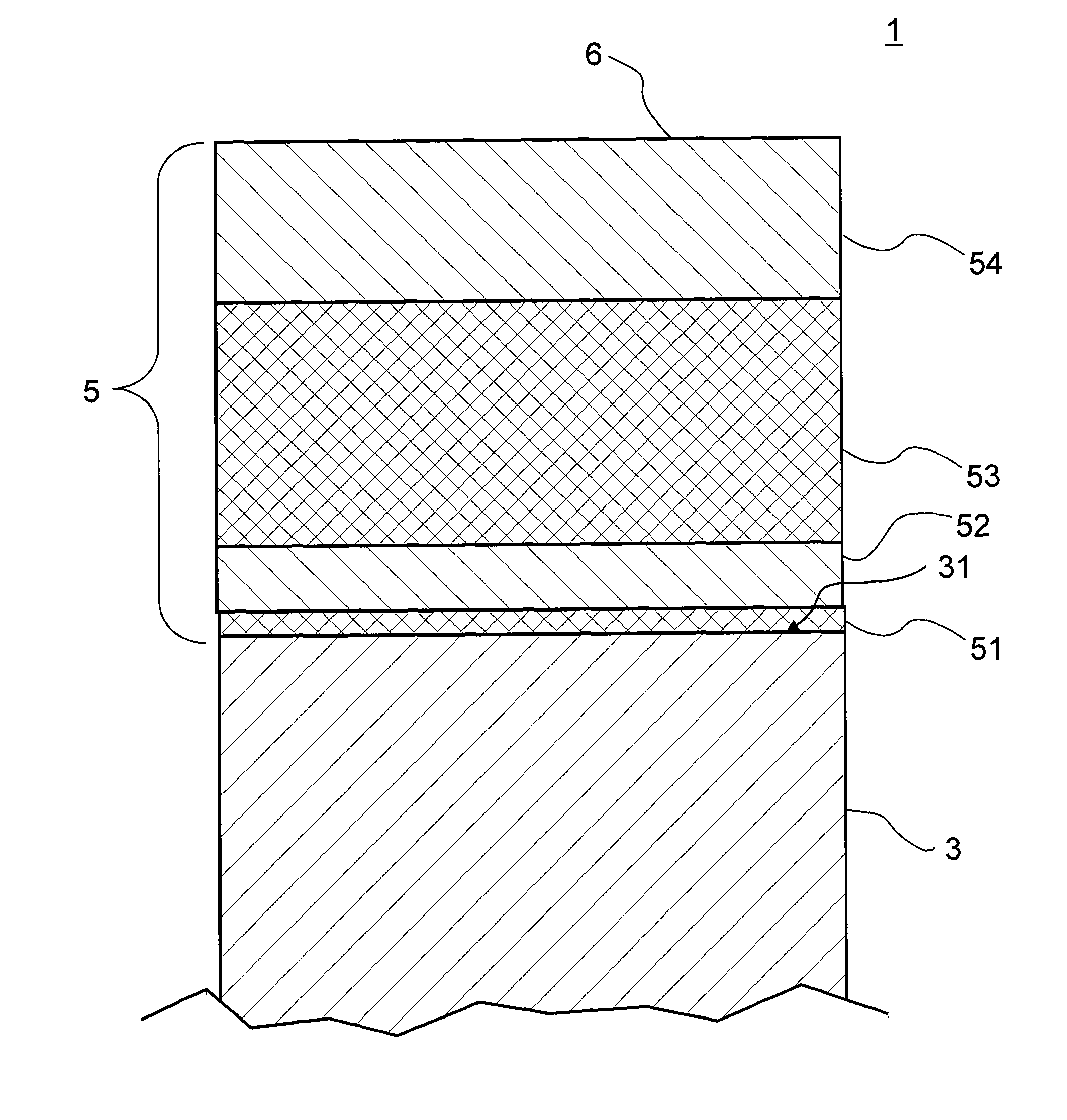
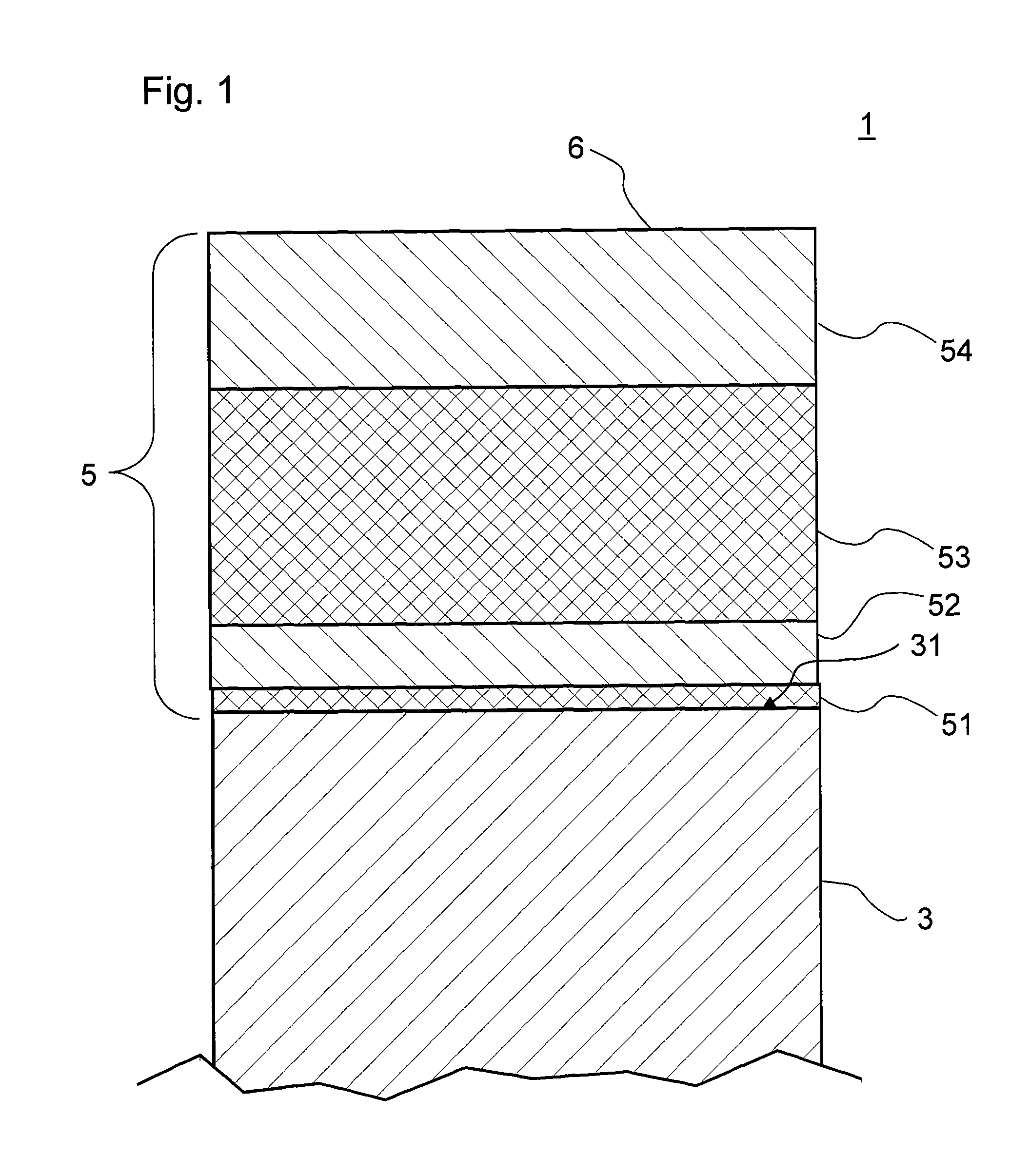
[0047]The example of a product 1 with a coated substrate 3 as shown in FIG. 1 is based on an antireflection coating 5 comprising a total of four layers. Typically, substrate 3 is pane- or plate-shaped, and antireflection coating 5 is deposited on one side 31 of substrate 3. In antireflection coating 5 layers having a higher refractive index alternate with layers having a lower refractive index. Here, layers 52, 54 are composed of silicon oxide with a proportion of aluminum so that the ratio of the amounts of aluminum to silicon is greater than 0.05, preferably greater than 0.08, but with the amount of silicon predominating the amount of aluminum. Preferably, the ratio of the amounts of aluminum to silicon is about 0.075 to 0.125, more preferably about 0.1. Thus, these layers 52, 54 function as low refractive index layers, because they primarily include silicon oxide.

[0048]Layers 51, 53, on the other hand, are layers having a higher refractive index and comprise silicon nitride, also...


PUM

PropertyMeasurementUnit
areaaaaaaaaaaa
root mean squared roughnessaaaaaaaaaa
thicknessaaaaaaaaaa

Abstract

A substrate is provided with an abrasion resistance antireflection coating. The coated substrate includes a multilayer antireflection coating on at least one side. The coating has layers with different refractive indices, wherein higher refractive index layers alternate with lower refractive index layers. The layers having a lower refractive index are formed of silicon oxide with a proportion of aluminum, with a ratio of the amounts of aluminum to silicon is greater than 0.05, preferably greater than 0.08, but with the amount of silicon predominant relative to the amount of aluminum. The layers having a higher refractive index include a silicide, an oxide, or a nitride.

Description

CROSS REFERENCE TO RELATED APPLICATIONS[0001]This application claims benefit under 35 U.S.C. §119(a) of German Patent Application No. 10 2011 012 160.9-45, filed Feb. 23, 2011 and of German Patent Application No. 10 2012 000 997.6, filed Jan. 20, 2012, the entire contents of both which are incorporated herein by reference.BACKGROUND OF THE DISCLOSURE[0002]1. Field of the Disclosure[0003]The invention generally relates to antireflection coatings and to substrates provided with antireflection coatings. In particular, the invention relates to antireflection coatings with high resistance to scratching and other abrasions.[0004]2. Description of Related Art[0005]Antireflection coatings are widely used today for improving the transmission of transparent substrates such as sight-glass windows, or on the other hand for diminishing annoying reflections on the substrate. However, depending on the intended use of the substrate, the antireflection coating might be exposed to high wearing stress...

Claims


Application Information

Patent Timeline
Patent Type & Authority Patents(United States)
IPC IPC(8): C03C17/34H01J37/34G02B1/115
CPCC03C17/3435G02B1/115H01J37/3467C03C2217/734C03C2217/77C03C17/3417C03C17/3482C03C2217/78C03C2218/156C03C2218/154C23C14/08C23C14/185C23C14/3485C23C14/35G02B1/116
Inventor HENN, CHRISTIANDAMM, THORSTEN
Owner SCHOTT AG
Learn More