
Optical waveguide device

a waveguide and optical technology, applied in the field of optical waveguide devices, can solve the problems of easy inability to be used as optical devices in communication fields, and remarkably degradation of optical characteristics

Active Publication Date: 2016-04-05
SUMITOMO OSAKA CEMENT CO LTD
View PDF28 Cites 2 Cited by
  • Summary
  • Abstract
  • Description
  • Claims
  • Application Information

AI Technical Summary

Benefits of technology

The present invention provides an optical waveguide device with a structure that reduces light leakage and prevents degradation of optical characteristics. The device includes a first branch portion that branches light into two light rays at a specific angle, two branched waveguides connected to the first branch portion, a radiation light guiding waveguide between the two branched waveguides, and an optical termination portion that guides or absorbs the radiation light. These features help to prevent light leakage and improve the performance of the optical waveguide device.

Problems solved by technology

However, when the substrate is thin, the optical characteristics are easily degraded (unstable) compared to an optical modulator including a thick substrate.
In addition, the optical waveguide in which light leakage occurs from an S-shaped portion has wavelength dependency, and thus is not able to be typically used as an optical device in a communication field.
Further, when a thinning structure is used in which the substrate is thinned, as described above, the optical characteristics are remarkably degraded.

Method used


Image

  • Optical waveguide device
  • Optical waveguide device
  • Optical waveguide device

Examples


Embodiment Construction

[0039]Hereinafter, the optical waveguide device of the present invention will be described in detail by using preferred examples.

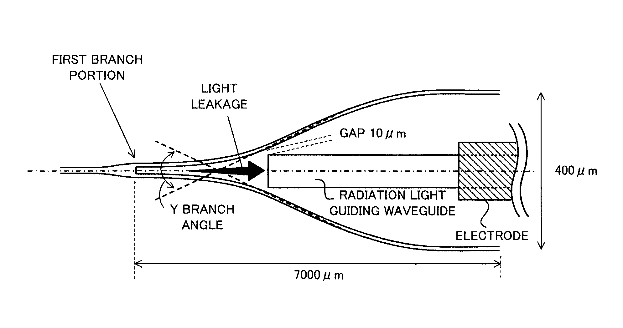
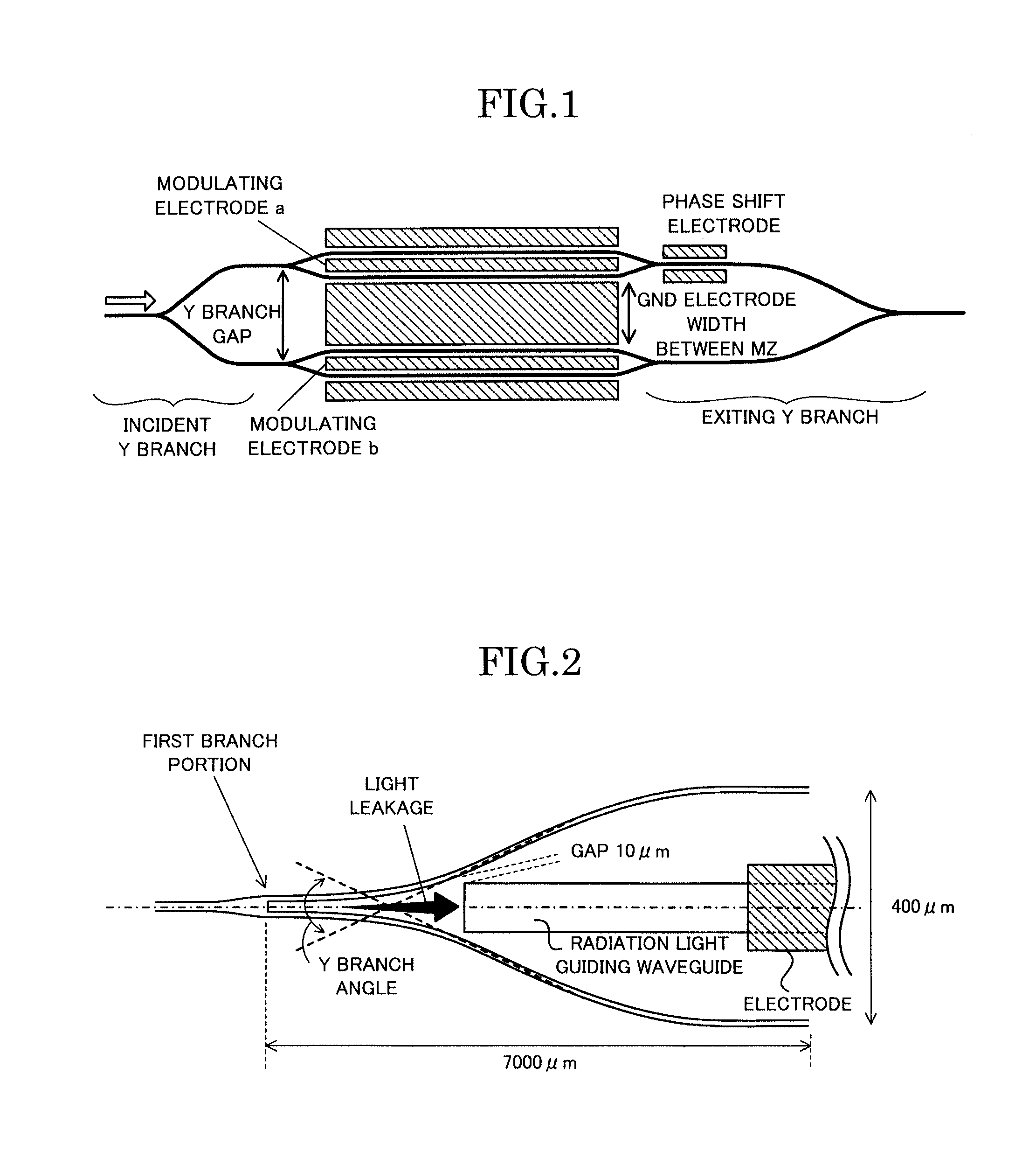
[0040]As illustrated in FIG. 2, the optical waveguide device of the present invention is an optical waveguide device in which an optical waveguide is formed on a substrate, the optical waveguide includes a first branch portion which branches light into two light rays at a branch angle of 1 / 35 rad or more, a second branch portion and a third branch portion are arranged to be connected to each of two branched waveguides branched from the first branch portion, a radiation light guiding waveguide is arranged between the two branched waveguides of the first branch portion, and guides radiation light radiated from between the two branched waveguides at the first branch portion to the outside of the optical waveguide, and an optical termination portion which absorbs the guided radiation light or emits the guided radiation light to the outside of the substrate is ...


PUM

PropertyMeasurementUnit
widthaaaaaaaaaa
distanceaaaaaaaaaa
thicknessaaaaaaaaaa

Abstract

An optical waveguide device in which optical characteristics are less degraded even when a branch angle in a Y branch portion of an optical waveguide is great is provided.In an optical waveguide device in which an optical waveguide is formed on a substrate, the optical waveguide includes a first branch portion which branches light into two light rays at a branch angle of 1 / 35 rad or more, a second branch portion (not illustrated) and a third branch portion (not illustrated) are arranged to be connected to each of two branched waveguides branched from the first branch portion, a radiation light guiding waveguide is arranged between the two branched waveguides of the first branch portion, and guides radiation light radiated from between the two branched waveguides at the first branch portion to the outside of the optical waveguide, and an optical termination portion (an electrode) which absorbs the guided radiation light or emits the guided radiation light to the outside of the substrate is arranged in a termination portion of the radiation light guiding waveguide.

Description

TECHNICAL FIELD[0001]The present invention relates to an optical waveguide device, and in particular, relates to an optical waveguide device in which optical characteristics are improved even when a branch angle in a Y branch of an optical waveguide is great.BACKGROUND ART[0002]In optical communication or optical information processing, an optical waveguide device is used in which an optical waveguide is formed on a substrate having electro-optic effect as lithium niobate (LN) or the like.[0003]In an LN modulator which is an example of the optical waveguide device, a shape of a waveguide is in a Mach-Zehnder (MZ) structure. A modulator having a MZ structure controls on / off of light by an applied voltage which is applied to a control electrode arranged along a branched optical waveguide of a MZ structure. Specifically, when an output waveguide of the waveguide having a MZ structure is a single mode waveguide, on / off of the light is able to be performed by fundamental mode and excited...

Claims


Application Information

Patent Timeline
Patent Type & Authority Patents(United States)
IPC IPC(8): G02F1/01G02B6/125G02F1/225G02F1/035G02F1/21
CPCG02B6/125G02F1/225G02F1/035G02F2001/212G02F2202/20G02F1/212G02F2201/08
Inventor KONDOU, KATSUTOSHI
Owner SUMITOMO OSAKA CEMENT CO LTD
Learn More