Surgical suture system, tissue restraints, and tissue anchors

a surgical suture and anchorage technology, applied in the field of surgical suture systems, tissue restraints, and tissue anchorages, can solve the problem that the suture cannot travel through the locking aperture from the exit side to the entrance side without complete suture failur

Active Publication Date: 2016-04-12
ZIPTEK
View PDF34 Cites 35 Cited by
  • Summary
  • Abstract
  • Description
  • Claims
  • Application Information

AI Technical Summary

Benefits of technology

[0059]FIG. 28 and FIG. 29 depict alternate aspects of the invention utilized to effect the repair shown in FIG. 27.
[0060]FIGS. 30 and 31 depict sagittal views depicting alte...

Problems solved by technology

In addition, the suture cannot travel through the locking apertu...

Method used


Image

  • Surgical suture system, tissue restraints, and tissue anchors
  • Surgical suture system, tissue restraints, and tissue anchors
  • Surgical suture system, tissue restraints, and tissue anchors

Examples


embodiment 67

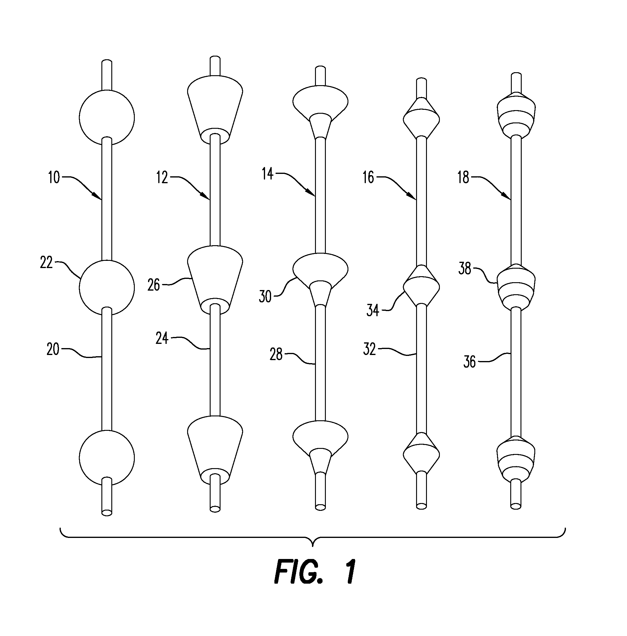
[0503]In FIG. 7A, another suture tissue restraint is there shown generally at numeral 67 or 67′ and formed having a domed-shaped body similar to that shown in FIG. 7. However, in this embodiment 67 / 67′, two spaced apart suture locking apertures 58′ are formed through the dome portion of the tissue restraint 67 / 67′ in closely spaced relationship facing the tissue engaging side of this tissue restraint 67 so that a suture may be tensioned upwardly or away from the tissue contact surface. However, the bevels of the suture locking apertures 58′ may be oriented oppositely one another to form suture tissue restraint 67′ to lockingly engage a single suture for one directional movement only. Note that, if formed as shown without the missing portions, these suture tissue restraints may be snappingly engaged over a suture and they continue to function as above described.

[0504]Note that hereinbelow, tissue anchors and suture tissue restraints are sometimes collectively referred to as “tissue e...

embodiment 400

[0540]In FIGS. 65 and 66, an alternate embodiment to that shown in FIG. 59 is shown generally at numeral 400′ which includes substantially the same elements of embodiment 400 except for the addition of an elastic resilient O-ring 420 tightly fitted into an annular grove 422 formed inwardly into each of the solid segments 402′. The O-ring 420 has a relaxed diameter smaller than that of the annular grove 422 such that, when stretched into place within the annular grove 422, resistance to elastically stretching the diameter of the suture-locking aperture 404 is increased.

[0541]In FIGS. 67 to 73, two embodiments of a pie-shaped expandable suture tissue restraint are there shown at 430 and 430a. These embodiments, 430 and 430a, have a generally button or disk shaped body 432 and are preferably compatible with sutures having a spherical protuberance as described above and include a plurality of spaced apart rigid sectors 434 which are separated by very thin and thus resilient flat disk 43...

embodiment 580

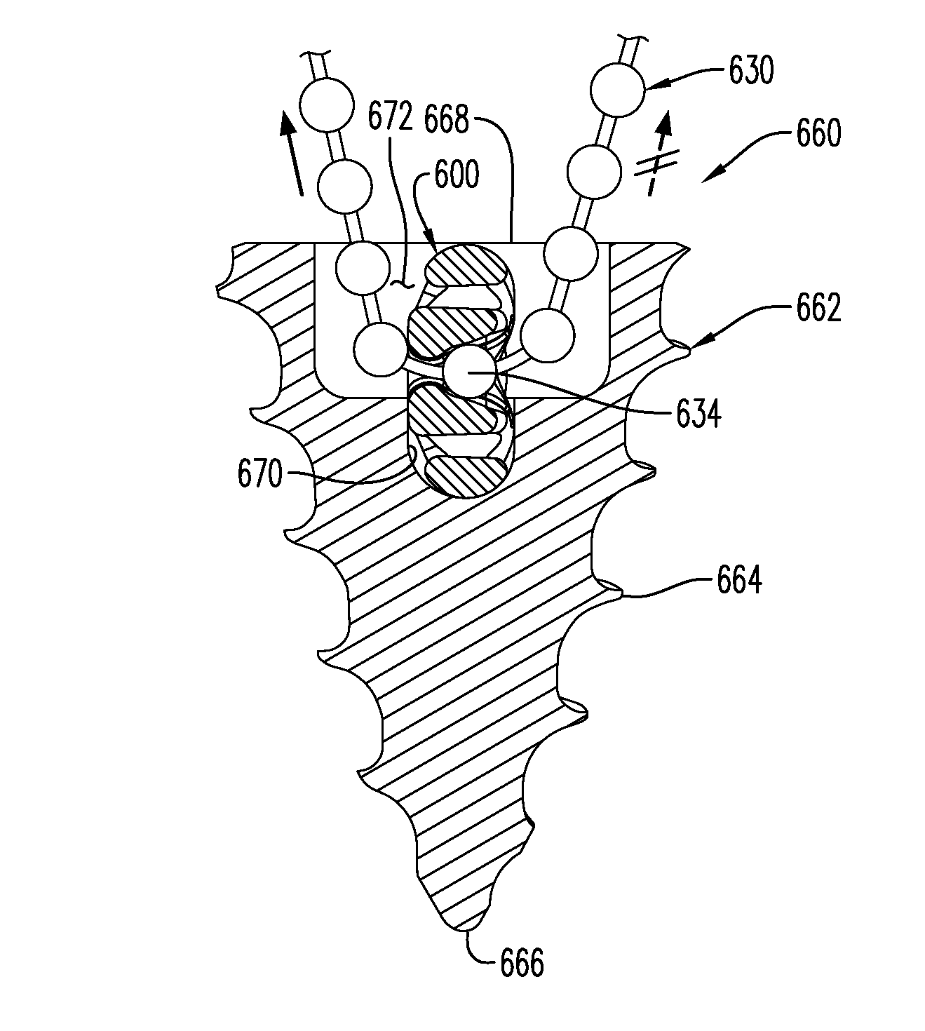
[0546]Referring to FIGS. 83 and 84, another embodiment of the tissue anchor is there shown at numeral 580. This exemplary embodiment 580 includes a solid tapered spiral thread 582 having a distal tissue penetrating tip 584 and a tapered head 586 formed having an axially aligned driving socket 594 formed into the proximal end of the tissue anchor 580. This embodiment 580 utilizes the resilient protuberance concept previously described in FIGS. 77 to 82, wherein the suture passage 588 is arcuately configured for smooth passage of the resiliently collapsed protuberances 464′ as they are forced against the head deforming inlet surface 590 as the suture is pulled in the direction of the arrow. Reverse movement of the suture is prohibited by the interaction of surface 470 of the backside of each protuberance 464 against the head locking surface 492.

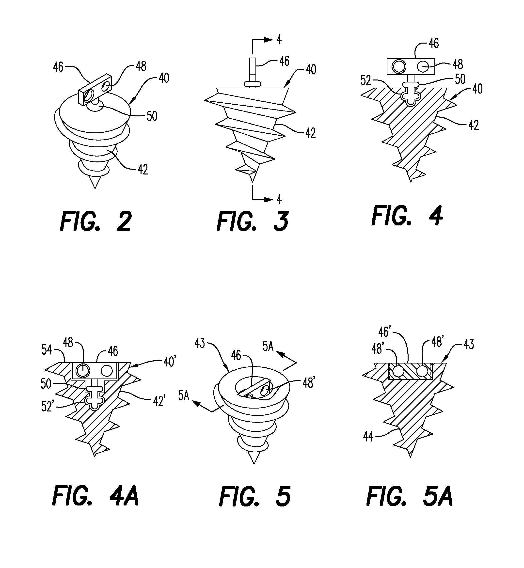
[0547]Referring now to the drawings, and firstly to FIGS. 85 to 90, the preferred embodiment of a tissue restraint / suture capture is there sho...


PUM


Abstract

A surgical suture system, tissue restraint/suture capture and tissue anchor for tissue repair and reattachment of torn tissue to a tissue substrate, medical, veterinary or dental prosthesis or medical implant. The system includes a plurality of tissue restraints/suture captures which each include a central locking aperture sized and configured to receive a beaded suture member passed therethrough which minimizes longitudinal tensioning and/or restraining movement, the “GO” force, of a beaded suture member in the forwardly direction through the locking apertures for suture tightening and which maximizes “NO-GO” force to pull the suture in the reverse direction. Uniquely configured tissue anchors and other medically implantable devices securely receive one of the tissue restraints/suture captures for tensioning of a suture member between tissue and the tissue anchor.

Description

CROSS-REFERENCE TO RELATED APPLICATIONS[0001]This application is a continuation-in-part of application Ser. No. 13 / 281,963, filed Oct. 26, 2011, which is a continuation-in-part of application Ser. No. 12 / 912,313, filed Oct. 26, 2010.STATEMENT REGARDING FEDERALLY SPONSORED RESEARCH OR DEVELOPMENT[0002]Not applicableINCORPORATION-BY-REFERENCE OF MATERIAL SUBMITTED ON A COMPACT DISC[0003]Not applicableBACKGROUND OF THE INVENTION[0004]1. Field of the Invention[0005]This invention relates generally to surgical apparatus and methods for repair of torn tissue, and more particularly to a system, components thereof, and method for arthroscopic and other surgical repair of torn tissue and tissue reattachment by providing the system for suturing and anchoring the torn tissue together against other tissue substrates, or for attaching tissue to medical, veterinary and dental implants.[0006]2. Description of Related Art[0007]The rotator cuff is composed of four tendons that blend together to help...

Claims


Application Information

Patent Timeline
IPC IPC(8): A61B17/04A61B17/06
CPCA61B17/06166A61B17/0401A61B17/0466A61B2017/045A61B2017/044A61B2017/0404A61B2017/0427A61B2017/0456A61B2017/0438A61B17/842A61B2017/0414A61B2017/0417A61B2017/0441A61B2017/0462A61B2017/06176A61F2/3662A61F2002/368
Inventor BENNETT, WILLIAM F.GALAZ MENDEZ, RAMSESGOMEZ ROMO, DANIEL FRANCISCO
Owner ZIPTEK
Why Eureka
Try Eureka