Fuel delivery system

a fuel delivery system and fuel delivery technology, applied in the direction of efficient propulsion technologies, machines/engines, instruments, etc., can solve the problems of increasing the cost of fuel consumption, affecting the efficiency of propulsion technology, and introducing significant weight into the engine, so as to reduce the optical depth of the contrail

Active Publication Date: 2016-04-12
ROLLS ROYCE PLC
View PDF28 Cites 8 Cited by
  • Summary
  • Abstract
  • Description
  • Claims
  • Application Information

AI Technical Summary

Benefits of technology

[0027]Any or a combination of the first and / or second searches may be used. The controller may comprise a first and / or second search algorithm, which may comprise a pre-search algorithm and / or optimisation algorithm. The pre-search algorithm may identify a sub-region of the available search space corresponding to lower environmental impact. The optimisation algorithm may be limited to a search within the identified sub-region for the optimum fuel blend. The combination of the pre-search and optimisation routines can provide for quicker convergence on an optimal fuel blend with minimal environmental impact.
[0031]The controller may select from within the searched range of fuel compositions a final fuel composition which offers a minimum value of the sensed vapour trail characteristic or else which meets a predetermined threshold vapour trail characteristic value, which may be a zero value. The controller may aim to minimise contrail optical depth.

Problems solved by technology

It may be undesirable for some ships to produce vapour trails in certain situations.
The attempted suppression of vapour trail formation through the reduction of exhaust water vapour content through use of a heat exchanger and condenser arrangement (US2008072577A) potentially introduces significant weight into the engine.
Furthermore, the weight penalty is incurred throughout the full duration of a flight, even though vapour trail suppression may only be required for a small percentage of the flight time.
Attempted suppression of vapour trail formation through the use of directed electromagnetic energy (US2010132330A) into the engine exhaust plume could incur a weight penalty.
Furthermore, the energy required to operate the system could represent a significant portion of the engine power and thus incur a fuel-burn penalty.
Further, in military applications, the emission of powerful electromagnetic radiation has the undesirable effect of increasing the aircraft's detectability.
Attempted suppression of vapour trail formation through the use of ultrasound directed into the engine exhaust plume (US2010043443A) may also incur a material weight penalty associated with equipment for generating the required sound levels.
The attempted modification or suppression of vapour trails through the use of chemicals (U.S. Pat. No. 5,005,355A, U.S. Pat. No. 4,766,725A, U.S. Pat. No. 3,517,505A, U.S. Pat. No. 3,517,512A, US2009013591A) injected either into the engine (whether with the fuel or separately from the fuel) or into the exhaust plume presents the prospect of additional pollution, incurs a weight penalty through the need to carry fuel additives with potentially little or no calorific value of their own (in comparison with conventional aviation fuel when burned within the engine), and may present challenges to engine reliability and / or component life.
The strategy of avoiding regions prone to vapour trail formation and / or persistence through the routing of aircraft around, above and / or below such regions has the disadvantage that it increases workload for air traffic control and / or pilots, reduces airspace capacity and, in the case of routing around regions prone to vapour trail formation or persistence (which can be tens or hundreds of kilometers in horizontal extent), the length of the route followed by the aircraft is increased, resulting in a fuel-burn penalty.
However, biofuels are typically much more expensive than conventional fuels and are in extremely short supply.
Hence it is undesirable to fuel a vehicle with biofuel throughout its period of operation, especially as the vehicle it powers may operate for much of its time in conditions where vapour trails will not form and / or persist regardless of the fuel used.

Method used


Image

  • Fuel delivery system
  • Fuel delivery system
  • Fuel delivery system

Examples


Embodiment Construction

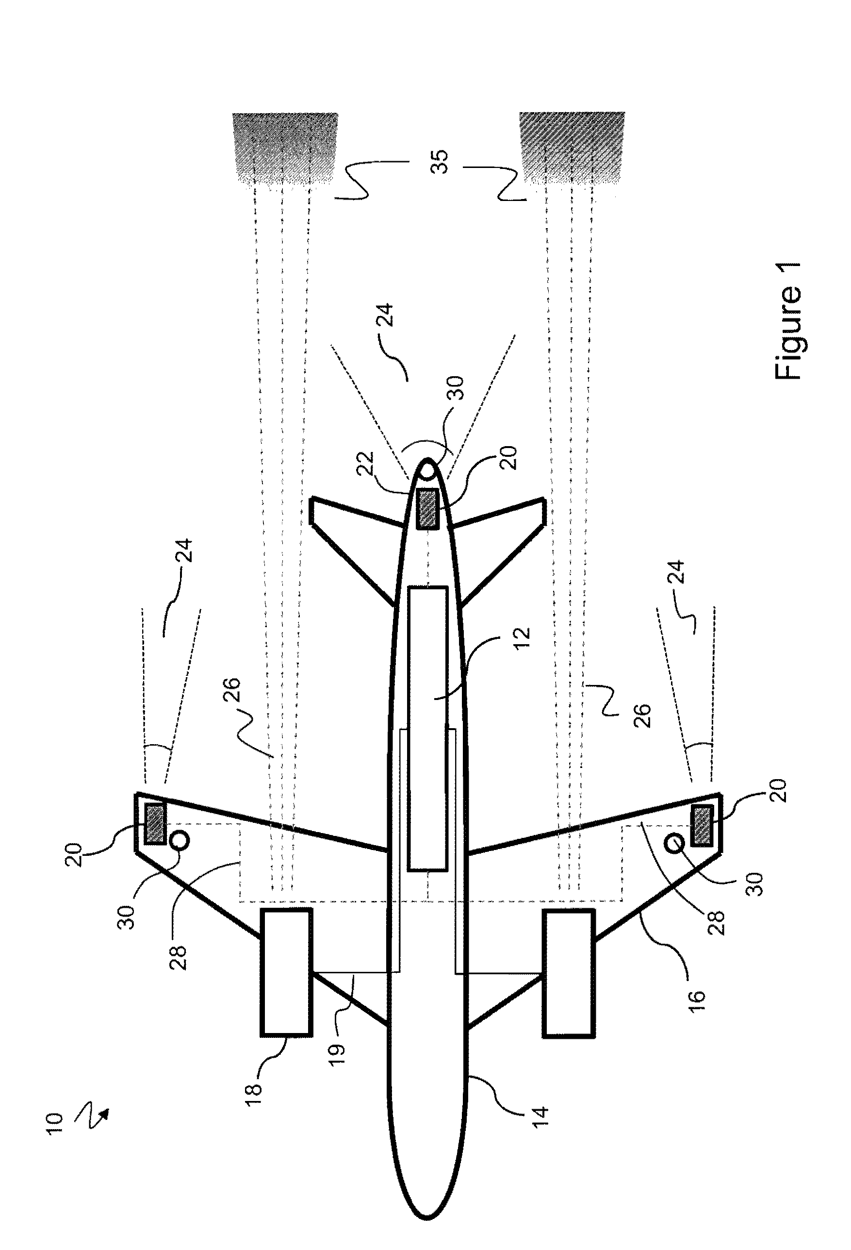
[0046]FIG. 1 shows a machine 10, in this example an aircraft, which comprises a fuel system 12 according to the present disclosure. In the example shown the aircraft comprises a fuselage 14 from which wings 16 extend, with engines 18 mounted to the wings. Other examples might involve alternative aircraft configurations, and different numbers of engines. The majority of the fuel system 12 is shown located in the fuselage 14. In alternative examples the fuel system 12 may be located elsewhere in the machine 10. Fuel pipes 19 fluidly connect the fuel system 12 and engines 18.

[0047]The fuel system 12 comprises at least one vapour trail detection sensor 20. In the example shown in FIG. 1, vapour trail detection sensors 20 are mounted towards the rear of the aircraft 10 facing aft. For example they are located at the tip of one or both wings 16 and / or at a trailing edge 22 of the fuselage. The, or each, vapour trail detection sensor 20 is mounted such that it has a field of view directed ...


PUM

PropertyMeasurementUnit
volumeaaaaaaaaaa
temperatureaaaaaaaaaa
humidityaaaaaaaaaa

Abstract

This invention concerns a fuel delivery system for an engine, in which two or more discrete fuel compositions are made available to the engine. The system has a vapor trail detection sensor configured to generate a detection signal indicative of a characteristic of a vapor trail. A regulator is configured to regulate a percentage of a first and a second fuel composition delivered to the engine as resultant fuel composition. A controller is arranged to undertake a search of trial fuel compositions by controlling the regulator to deliver to the engine a plurality of trial fuel compositions having different ratios of the first and second fuel compositions. The controller controls delivery of a resultant fuel composition to the engine in response to the vapor trail characteristic detection signals for said plurality of trial fuel compositions.

Description

BACKGROUND OF THE INVENTION[0001]The present invention relates to a machine fuel delivery system and method, typically, although not exclusively, for aircraft engines.[0002]Vapour trails are artificial clouds that are visible trails of condensed water vapour exhausted by vehicles' engines. They may be formed as warm, moist exhaust gas mixes with ambient air, and arise from the precipitation of microscopic water droplets or, if the air is cold enough, tiny ice crystals. The term “vapour trails” is intended to refer both to condensation trails (that is to say “contrails”) from aircraft and to water and / or ice precipitation in or attributable to the exhaust plumes from engines of other machines and vehicles, such as ships.[0003]It may be undesirable for some ships to produce vapour trails in certain situations. For example, a military ship producing a vapour trail from its exhaust funnels is highly visible from the air and hence much easier to target.[0004]It is understood that, depend...

Claims


Application Information

Patent Timeline
Patent Type & Authority Patents(United States)
IPC IPC(8): F02C9/28G01N21/53F02C3/20F02C7/22F02C9/40
CPCF02C3/20F02C7/22F02C9/40G01N21/538F02C9/28F05D2270/081F05D2270/082Y02T50/60
Inventor SWANN, PETER
Owner ROLLS ROYCE PLC
Why Eureka
Try Eureka