Showerhead for film depositing vacuum equipment

a vacuum equipment and film-depositing technology, which is applied in the direction of lighting and heating equipment, combustion types, coatings, etc., can solve the problems of warping in the tubes, difficulty in assembly during fabrication processes or maintenance of the showerhead, and non-uniform deposition, so as to shorten the length of the reaction injection tubes connected from the bottom of the reactive gas showerhead modul

Active Publication Date: 2016-04-19
KOREA INST OF IND TECH
View PDF13 Cites 349 Cited by
  • Summary
  • Abstract
  • Description
  • Claims
  • Application Information

AI Technical Summary

Benefits of technology

[0018]Accordingly, the present invention has been made keeping in mind the above problems existing in the related art, and is intended to provide a showerhead for film-depositing vacuum equipment, in which a reactive gas showerhead module is disposed above a cooling jacket while defining a purge gas redistribution space between the reactive gas showerhead module and the cooling jacket, a purge gas showerhead module is disposed above the reactive gas showerhead module, so that the length of reactive gas injection tubes, which are connected from the bottom of the reactive gas showerhead module, can be decreased, thereby overcoming problems, such as warping of the tube or difficulty in assembling during fabrication processes or maintenances of the showerhead. It is also possible to overcome the problems of pressure loss caused by increased length of the reactive gas injection tubes, difficulty in properly supplying the reactive gas, and remaining of the reactive gas in the former process inside the showerhead when depositing several layers of a film.
[0019]The present invention is also intended to provide a showerhead for film-depositing vacuum equipment, in which reactive gases are mixed together inside one reactive gas showerhead module, as long as they have similar properties such that they do not undergo a chemical reaction and thus rarely form particles inside the reactive gas showerhead module. As a result, this can keep the number of the reactive gas showerhead modules low even though kinds of reaction gases increases, thereby solving the problems associated with the overall configuration and assembly of the showerhead and the problem resulting from the limited space inside the reaction chamber.
[0025]As described above, the reactive gas showerhead module is disposed above the cooling jacket, the purge gas showerhead module is disposed above the reactive gas showerhead module, and the injection tubes of the reactive gas showerhead module extend through the cooling jacket below, such that the purge gas is introduced into the purge gas redistribution space between the reactive gas showerhead module and the cooling jacket. The length of the reaction injection tubes connected from the bottom of the reactive gas showerhead module can thus be shortened. Consequently, it is possible to overcome problems, such as a warping of the tube or difficulty in assembling during fabrication processes or maintenances of the showerhead. It is also possible to overcome the problems of pressure loss caused by increased length of the reactive gas injection tubes, difficulty in properly supplying the reactive gas, and remaining of the reactive gas in the former process inside the showerhead when depositing several layers of a film.
[0026]Furthermore, a plurality of reactive gases can be introduced to one reactive gas showerhead module through a plurality of inlets of one reactive gas showerhead module as long as they do not undergo a chemical reaction and rarely form particles even though they are mixed together inside the reactive gas showerhead module. Thus, the reactive gases having similar properties can be injected by being mixed together inside one reactive gas showerhead module. As a result, this can keep the number of the reactive gas showerhead modules to a minimum even though kinds of reaction gases increases, thereby solving the problems associated with the overall configuration and assembly of the showerhead resulting from the limited space inside the reaction chamber.

Problems solved by technology

Otherwise, it may result in unintended particle deposition on some portion of the showerhead and cause a non-uniformity of deposition.
The presence of Δl that has to be basically included may cause drawbacks, such as warping in the tubes or difficulty in assembling during fabrication processes or maintenances of the showerhead.
In an example, a large pressure drop may make it difficult to efficiently supply the reactive gas to the substrate.
However, there is a possibility that the changed process gas may flow back towards the former process gas line.
As long as different kinds of process gases are commonly used in one process gas supply tube, the problem of contamination still exists.
In this configuration, however, an increase in the number of reactive gases which constitute the elements of the film may result in the showerhead of a complicated structure. FIG. 1 shows that the two reactive gas showerhead modules 110 and 120 are stacked in the vertical direction.
However, continuously increasing the number of the reactive gas showerhead modules in response to an increase in kinds of the reactive gases may cause a problem due to the limited space allocated to the inside of the reaction chamber.

Method used


Image

  • Showerhead for film depositing vacuum equipment
  • Showerhead for film depositing vacuum equipment
  • Showerhead for film depositing vacuum equipment

Examples


first embodiment

[0038]Hereinafter preferred embodiments of the present invention will be described in detail with reference to the accompanying drawings. FIG. 5 shows a showerhead for film-depositing vacuum equipment according to the present invention, including one purge gas showerhead module 10, one reactive gas showerhead module 20 and one cooling jacket 30.

[0039]As shown in FIG. 5, the showerhead of the first embodiment is constructed by sequentially stacking one purge gas showerhead module 10, one reactive gas showerhead module 20 and one cooling jacket 30 in the vertical direction from top to bottom, on the assumption that one kind of reactive gas and one kind of purge gas shall be used.

[0040]The purge gas showerhead module 10 has an intermediate plate 13 between an upper plate 11 and a bottom plate 12 such that purge gas flows through an inlet 14 into the space between the upper plate 11 and the intermediate plate 13. Then, the purge gas, via a plurality of holes 13a in the intermediate plat...

second embodiment

[0051]The configuration of the second embodiment can be effectively used when kinds of reactive gases are increased in the film deposition process. A reactive gas that does not cause a delivering problem even under a considerable pressure drop is introduced into the upper reactive gas showerhead module 40 having relatively longer injection tubes 49. In contrast, a reactive gas that may experience undesirable influences by a pressure drop is introduced into the lower reactive gas showerhead module 20 having relatively shorter injection tubes 29.

[0052]FIG. 7 shows a third embodiment of the showerhead for film-depositing vacuum equipment according to the present invention, in which, in addition to the configuration of the first embodiment described above, another reactive gas showerhead module 50 is disposed above the purge gas showerhead module 10, and injection tubes 59 of the upper reactive gas showerhead module 50 extend sequentially through guide tubes 10a, 20b, and 30a of the low...

fourth embodiment

[0054]With the configuration of the fourth embodiment as above, a plurality of reactive gases can be introduced through a plurality of the inlets 25a and 25b. Therefore, it is possible to overcome problems associated with unnecessarily increasing the number of reactive gas showerhead modules 20 and problems resulting from the limited space inside the reaction chamber.

[0055]Here, it is preferable that the reactive gases introduced through the inlets 25a and 25b of the reactive gas showerhead module 20 are of a similar kind, rarely forming particles when mixed together. Then, such reactive gases are injected by being mixed together in one reactive gas showerhead module 20.

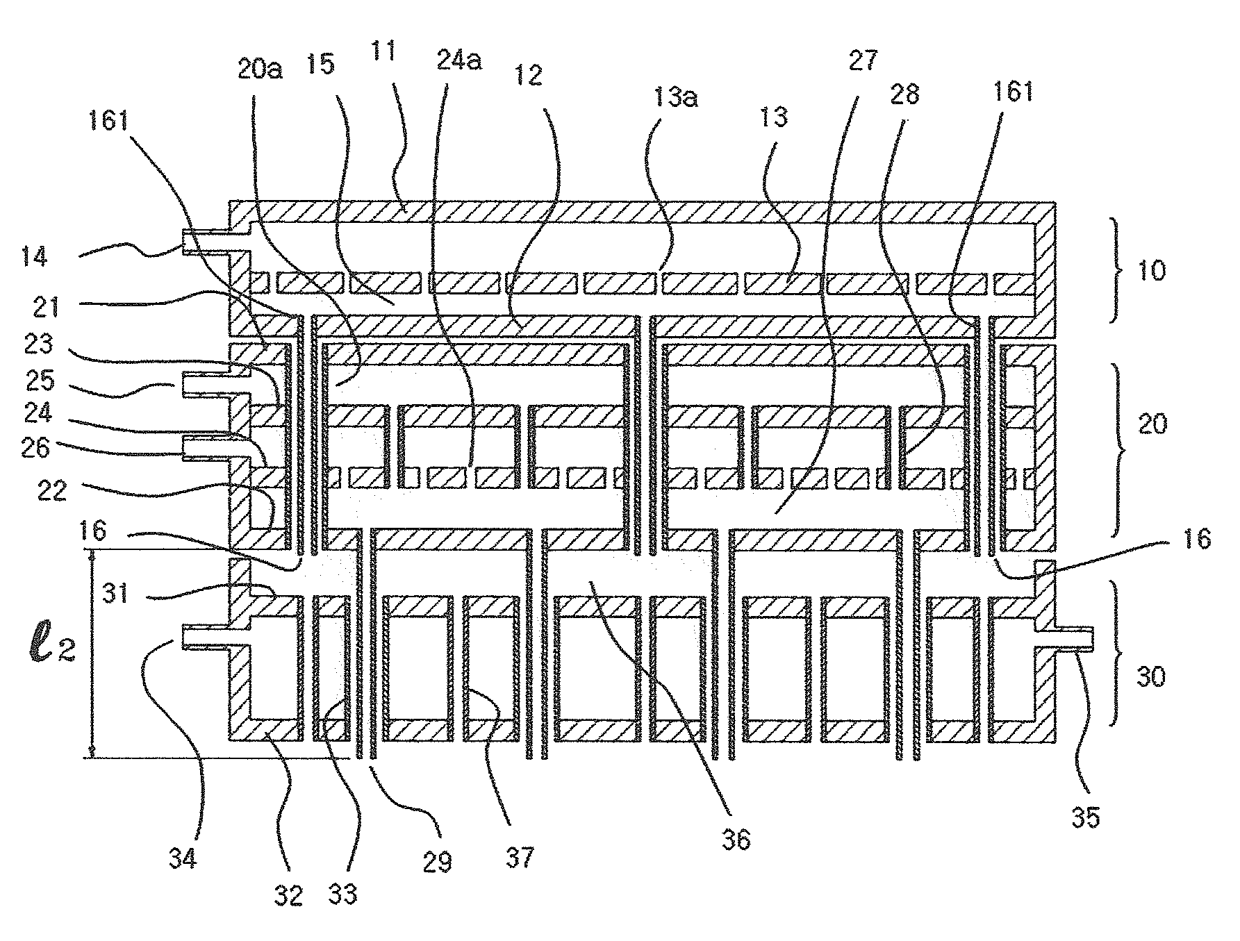
[0056]FIG. 9 shows a variation of the fourth embodiment of the present invention, in which the reactive gas showerhead module 20 has first and second intermediate plates 23 and 24 between the upper plate 21 and the bottom plate 22. With this configuration, an injection support gas is introduced through an inlet 26 in...


PUM

PropertyMeasurementUnit
temperatureaaaaaaaaaa
velocityaaaaaaaaaa
total flow rateaaaaaaaaaa

Abstract

A showerhead for film-depositing vacuum equipment having an effect shortening the length of injection tubes for a reactive gas is presented. The injection tubes extend from the bottom of a reactive gas showerhead module, and two different kinds of reactive gases are mixed with an injection support gas within a reactive showerhead module so as to inject the mixed gas. The showerhead for film-depositing vacuum equipment includes the reactive gas showerhead module above a cooling jacket and a purge gas showerhead module above the reactive gas showerhead module. The injection tubes of the reactive gas showerhead module pass through the cooling jacket disposed below the reactive gas showerhead module, and the injection tubes of the purge gas showerhead module pass through the reactive gas showerhead module disposed below the purge gas showerhead module, thereby enabling the purge gas to flow into a purge gas redistribution space defined above the cooling jacket.

Description

[0001]This application is a National Stage application of International Application No. PCT / KR2010 / 003024, filed on May 13, 2010, which claims priority of Korean Application Serial No. 10-2009-0048290 filed on Jun. 1, 2009.BACKGROUND OF THE INVENTION[0002]1. Field of the Invention[0003]The present invention relates to a showerhead for film-depositing vacuum equipment and, more particularly, to a showerhead for film-depositing vacuum equipment, which uniformly and stably supplies a process gas onto a substrate during a film deposition process, such as chemical vapor deposition, thereby improving the quality of the formed film and preventing the undesired deposition of particles.[0004]2. Description of the Prior Art[0005]In response to the ongoing high-integration of semiconductor devices, the need becomes stronger to control process parameters more precisely in fabrications of semiconductor devices including a film deposition process. Many efforts are done to achieve process reliabil...

Claims


Application Information

Patent Timeline
Patent Type & Authority Patents(United States)
IPC IPC(8): C23C16/455
CPCC23C16/45572C23C16/45574C23C16/45565C23C16/45576C23C16/45591C23C16/45563H01L21/02H01L21/205
Inventor BYUN, CHULSOOHAN, MAN CHEOLCHUNG, IL YONGLEE, SEOK WOO
Owner KOREA INST OF IND TECH
Why Eureka
Try Eureka